 Facebook
 Google
 GitHub
 Linkedin
Techniques for Analyzing Control Strategies
Control strategies such as cascade, ratio, feedforward, and those containing limit and selector functions can be quite daunting to analyze, especially for students new to the subject. As a teacher, I have seen first-hand where students tend to get confused on these topics, and have seen how certain problem-solving techniques work well to overcome these conceptual barriers. This section explores some of these techniques and the reasons why they work.
Explicitly denoting controller actions
The direction of action for a loop controller – either direct or reverse – at first seems like a very simple concept. It certainly is fundamental to the comprehension of any control strategy containing PID loop controllers, but this seemingly simple concept harbors an easy-to-overlook fact causing much confusion for students as they begin to analyze any control strategy where a loop controller receives a remote setpoint signal from some other device, most notably in cascade and ratio control strategies.
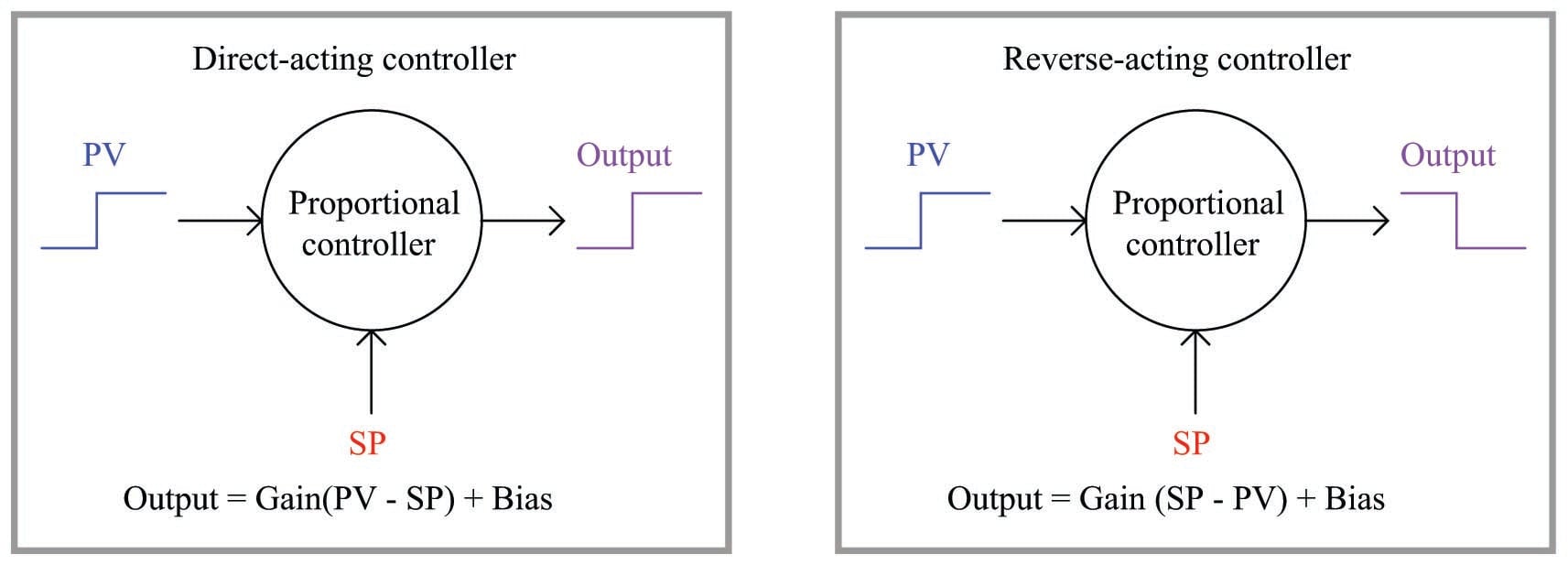
A direct-acting loop controller is defined as one where the output signal increases as the process variable signal increases. A reverse-acting controller is defined as one where the output signal decreases as the process variable signal increases. Both types of action are shown here:
Let us apply this concept to a realistic application, in this case the control of temperature in a steam-heated chemical reactor vessel:
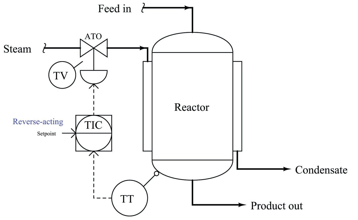
As the reactor vessel’s temperature increases, we need the temperature controller (TIC) to reduce the amount of hot steam entering the jacket in order to stabilize that temperature. Since the steam control valve is air-to-open (ATO), this means we need the controller to output a decreasing signal as the process variable (temperature) signal increases. This, by definition, is a reverse-acting controller. This example also showcases the utility of the problem-solving technique known as a “thought experiment,” whereby we imagine a certain condition changing (in this case, the reactor temperature increasing) and then we mentally model the desired response of the system (in this case, closing the steam valve) in order to determine the necessary controller action.
So far, this example poses no confusion. But suppose we were to perform another thought experiment, this time supposing the setpoint signal increases rather than the reactor temperature increases. How will the controller respond now?
Many students will conclude that the controller’s output signal will once again decrease, because we have determined this controller’s action to be reverse, and “reverse” implies the output will go the opposite direction as the input. However, this is not the case: the controller output will actually increase if its setpoint signal is increased. This, in fact, is precisely how any reverse-acting controller should respond to an increase in setpoint.
The reason for this is evident if we take a close look at the characteristic equation for a reverse-acting proportional controller. Note how the gain is multiplied by the difference between setpoint and process variable. Note how the process variable has a negative sign in front of it, while setpoint does not.
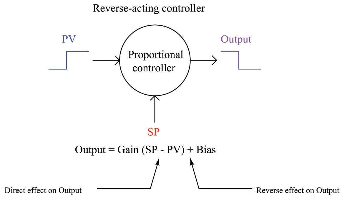
An increase in process variable (PV) causes the quantity inside the parentheses to become more negative, or less positive, causing the output to decrease toward 0%. Conversely, an increase in setpoint (SP) causes the quantity inside the parentheses to become more positive, causing the output to increase toward 100%. This is precisely how any loop controller should respond: with the setpoint having the opposite effect of the process variable, because those two quantities are always being subtracted from one another in the proportional controller’s equation.
Where students get confused is the single label of either “direct” or “reverse” describing a controller’s action. We define a controller as being either “direct-acting” or “reverse-acting” based on how it responds to changes in process variable, but it is easy to overlook the fact that the controller’s setpoint input must necessarily have the opposite effect. What we really need is a way to more clearly denote the respective actions of a controller’s two inputs than a single word.
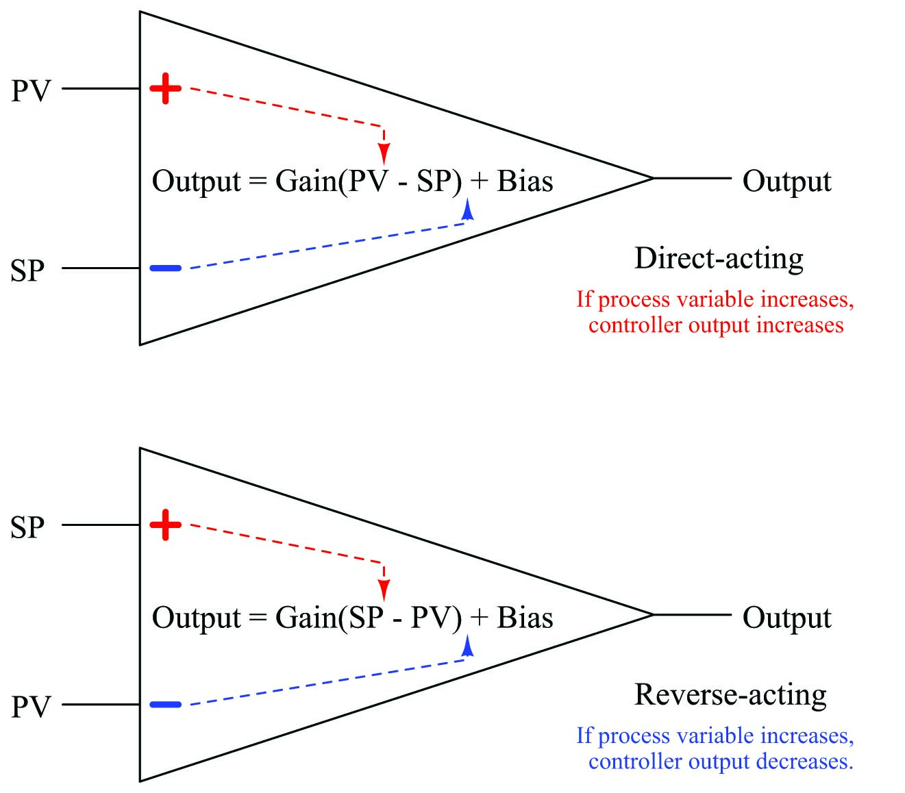
Thankfully, such a convention already exists in the field of electronics1023, where we must denote the “actions” of an operational amplifier’s two inputs. In the case of an opamp, one input has a direct effect on the output (i.e. a change in signal at that input drives the output the same direction) while the other has a reverse effect on the output (i.e. a change in signal at that input drives the output in the opposite direction). Instead of calling these inputs “direct” and “reverse”, however, they are conventionally denoted as noninverting and inverting, respectively. If we draw a proportional controller as though it were an opamp, we may clearly denote the actions of both inputs in this manner:
I strongly recommend students label the loop controllers in any complex control strategy in the same manner, with “+” and “\(-\)” labels next to the PV and SP inputs for each controller, in order to unambiguously represent the effects of each signal on a controller’s output. This will be far more informative, and far less confusing, than merely labeling each controller with the word “direct” or “reverse”.
Let us return to our example of the steam-heated reactor to apply this technique, labeling the reverse-acting controller’s process variable input with a “\(-\)” symbol and its setpoint input with a “+” symbol:
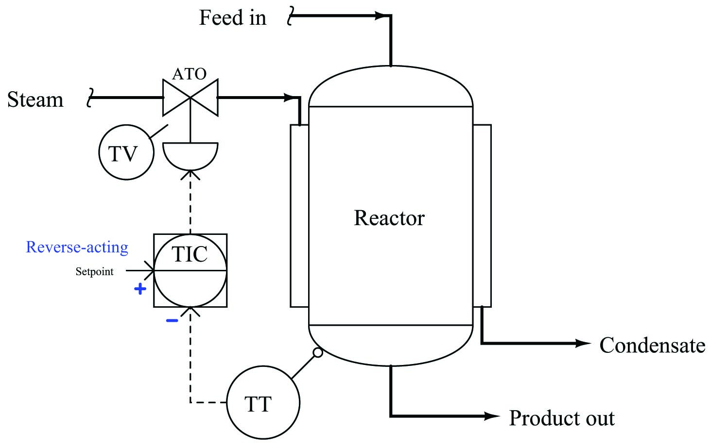
With these labels in place we can see clearly how an increase in temperature going into the “\(-\)” (inverting) input of the temperature controller will drive the valve signal down, counter-acting the change in temperature and thereby stabilizing it. Likewise, we can see clearly how an increase in setpoint going into the “+” (noninverting) input of the temperature controller will drive the valve signal up, sending more steam to the reactor to achieve a greater temperature.
While this technique of labeling the PV and SP inputs of a loop controller as though it were an operational amplifier is helpful in single-loop controller systems, it is incredibly valuable when analyzing more complex control strategies where the setpoint to a controller is a live signal rather than a static value set by a human operator. In fact, it is for this very reason that many students do not begin to have trouble with this concept until they begin to study cascade control, where one controller provides a live (“remote”) setpoint value to another controller. Up until that point in their study, they never rarely had to consider the effects of a setpoint change on a control system because the setpoint value for a single-loop controller is usually static.
Let us modify our steam-heated reactor control system to include a cascade strategy, where the temperature controller drives a setpoint signal to a “slave” steam flow controller:
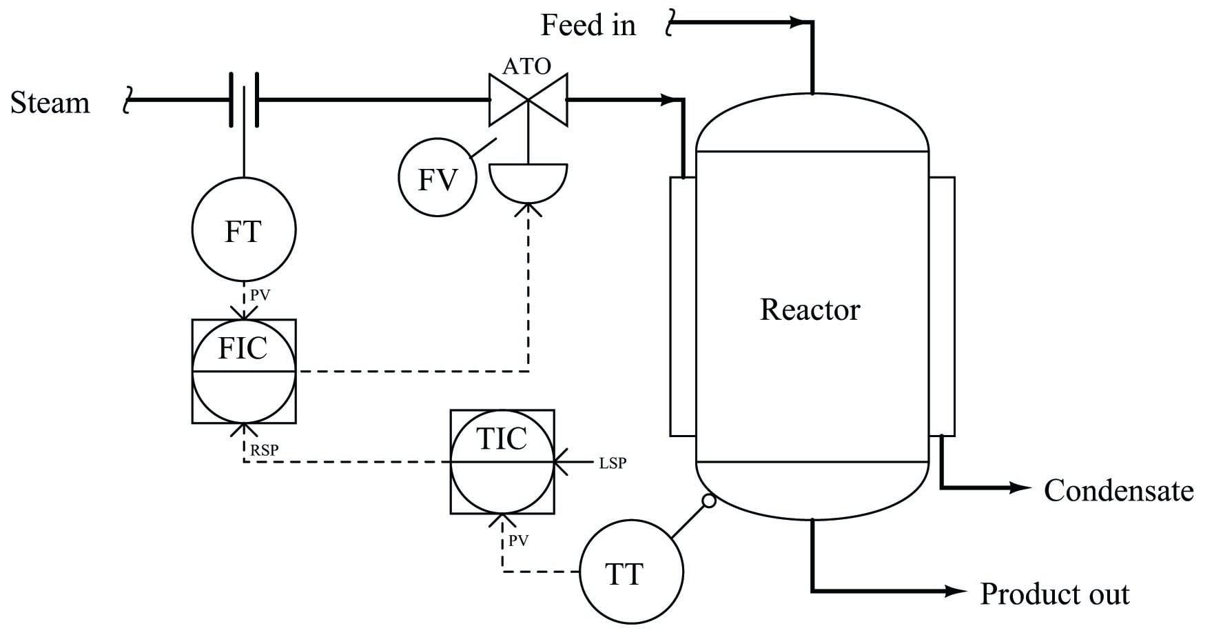
In order to determine the proper actions for each controller in this system, it is wise to begin with the slave controller (FIC), since the master controller (TIC) depends on the slave controller being properly configured in order to do its job properly. Just as we would first tune the slave controller in a cascade system prior to tuning the master controller, we should first determine the correct action for the slave controller prior to determining the correct action for the master controller.
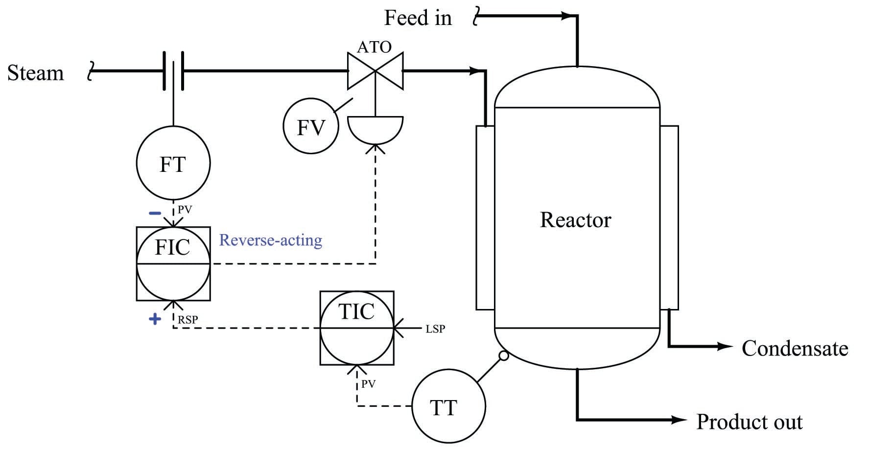
Once again we may apply a “thought experiment” to this system in order to choose the appropriate slave controller action. If we imagine the steam flow rate suddenly increasing, we know we need the control valve to close off in order to counter-act this change. Since the valve is still air-to-open, this requires a decrease in the output signal from the FIC. Thus, the FIC must be reverse-acting. We shall denote this with a “\(-\)” label next to the process variable (PV) input, and a “+” label next to the remote setpoint (RSP) input:
Now that we know the slave controller must be reverse-acting, we may choose the action of the master controller. Applying another “thought experiment” to this system, we may imagine the reactor temperature suddenly increasing. If this were to happen, we know we would need the control valve to close off in order to counter-act this change: sending less steam to a reactor that is getting too hot. Since the valve is air-to-open, this requires a decrease in the output signal from the FIC. Following the signal path backwards from the control valve to the FIC to the TIC, we can see that the TIC must output a decreasing signal to the FIC, calling for less steam flow. A decreasing output signal at the TIC enters the FIC’s noninverting (“+”) input, causing the FIC output signal to also decrease. Thus, we need the TIC to be reverse-acting as well. We shall denote this with a “\(-\)” label next to the process variable (PV) input, and a “+” label next to the local setpoint (LSP) input:
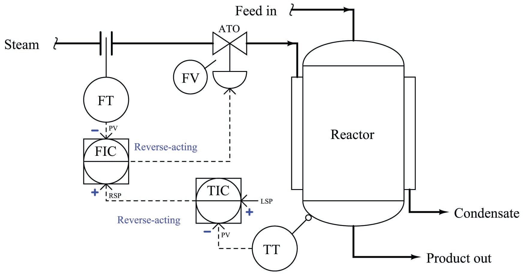
With these unambiguous labels in place at each controller’s inputs, we are well-prepared to qualitatively analyze the response of this cascade control system to process upsets, to instrument failure scenarios, or to any other change. No longer will we be led astray by the singular label of “reverse-acting”, but instead will properly recognize the different directions of action associated with each input signal to each controller.
Determining the design purpose of override controls
Override control strategies are a source of much confusion for students first learning the concept. Perhaps the most fundamental question students find difficult to answer when faced with an override strategy is how to determine the intended purpose for that strategy if no explanation is given.
Take for example this surge tank level/flow control system. While it may be obvious that the flow controller is there for the purpose of regulating flow out of the tank, it is not so clear what the two level controllers are doing, or what purposes are served by the two selector functions:
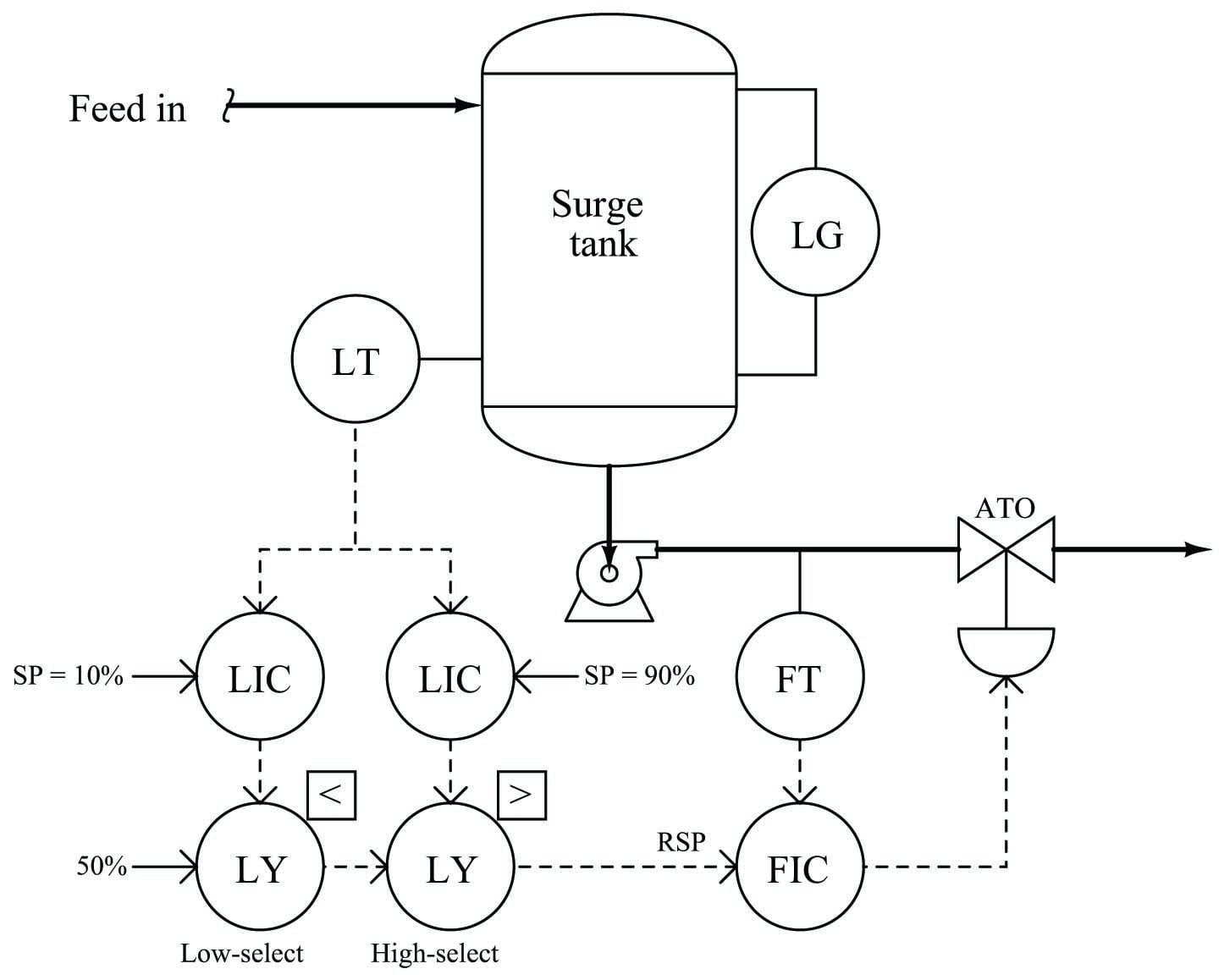
A good starting point in our analysis is to first determine the proper directions of action for each controller. This is wise because the selector functions perform their tasks based on the relative values of the controller output signals: controllers become selected or de-selected on the basis of their output signals being greater or less than some other signal. Therefore, before we may be able to determine the purpose of a selector function, we must know how the loop controller feeding that selector function is supposed to react to process conditions. Once we have determined each controller’s proper action, we may then interpret each selector’s function in light of what process conditions will cause a particular controller to become selected.
When choosing the proper action for each controller, we must consider each controller in this system – one at a time – as though it were the one being selected. In other words, we may give ourselves license to ignore the selector functions and just concentrate for the time being on how each controller needs to act in order to do its job when selected. Looking at the system from this perspective, we see that each level controller (when selected) acts as a master to the flow (slave) controller. Thus, what we have here is a cascade level/flow control system, with two master controllers selected on the basis of their output signals.
The flow controller (FIC) needs to be reverse-acting, because in order to counter-act an increase in flow rate it must close off the valve (i.e. decreasing output with increasing input = reverse action). Each level controller needs to be direct-acting, because in order to counter-act an increase in level it must call for more flow exiting the tank (i.e. increasing output with increasing input = direct action). Denoting these actions using “+” and “\(-\)” labels at each PV and SP input line:
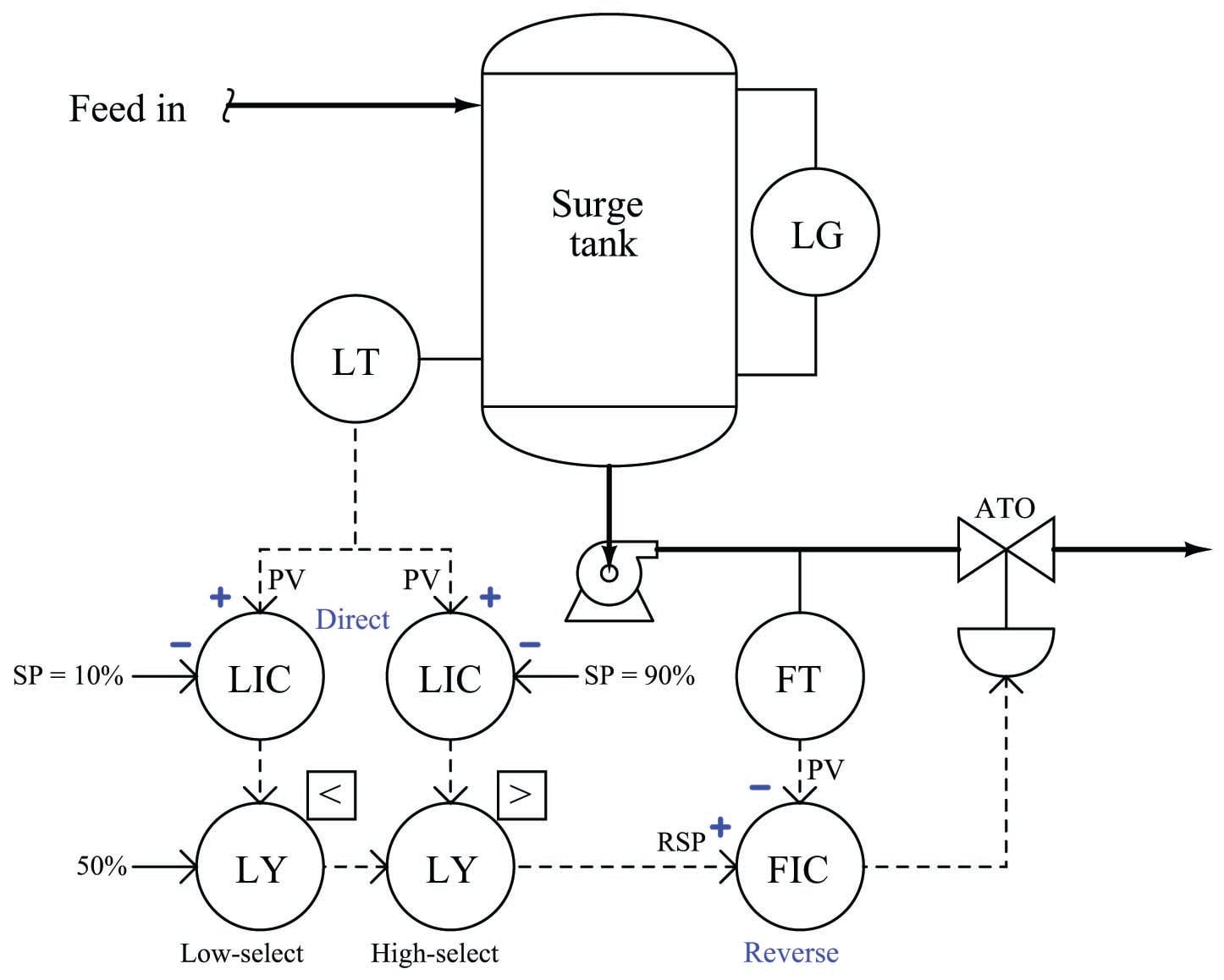
Only now are we prepared to analyze the purpose of each selector function. Let’s begin with the low-select first. It selects the lowest of two values, either a fixed value of 50% or the output of the level controller with the 10% setpoint. Since we know this level controller is direct-acting, we may conclude that it will be selected if it sees a low level at its PV input. More specifically, it will be surely be selected if the measured tank level drops significantly below the setpoint value of 10%. Thus, we may conclude that the purpose of this level controller is to take over control if the tank level reaches or drops below the 10% mark.
Next, let us analyze the purpose of the other level controller (connected to the high-select function). Since the high-select function will select this level controller only if its output signal exceeds the signal passed on by the low-select function, and we know that this controller is direct-acting, we may conclude that it will be selected if it sees a high level at its PV input. More specifically, it will surely be selected if the measured tank level rises significantly above the setpoint value of 90%. Thus, we may conclude that the purpose of this level controller is to take over control if the tank level reaches or exceeds the 90% mark.
If neither level controller is selected, the signal that gets passed on to the flow controller as a remote setpoint is the 50% fixed signal entering on the left-hand side of the low-select function. Thus, the flow controller tries to maintain a steady flow rate of 50% in the event neither level controller is selected.
Putting all these pieces together, we may conclude that the purpose of this surge tank control system is to maintain as steady a flow rate as possible out of the tank (and on to some other process), letting the liquid level inside the tank rise and fall significantly before any action is taken to change the flow rate. Only if the level drops below 10% will the flow rate be reduced, and only if the level rises above 90% will the flow rate be increased. Otherwise, the flow rate will hold steady at 50%.
To summarize, the recommended technique for analyzing the purpose of an override control system is as follows:
- First, determine the necessary actions of each controller (assume the selector functions are absent, and each controller gets its turn controlling the process).
- Identify the type of selection (high or low) implemented by each selector function.
- Based on the type of selection and the action of the controller, identify what process condition will cause that controller to become selected. This is the condition the controller exists to regulate.
