A question about IGV and 2nd stage nozzles fail position and opening angle?

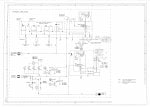
Hello, in our site we we have several GE MS5002D gas turbines running. I have a problem in understating the working principle of some components in the turbine. MS5002D is a two shaft turbine that utilizes Inlet guide vanes (IGV) mounted to the front of the axial air compressor and also a variable angles second stage nozzles mounted before the 2nd stage turbine wheel. According to my P&ID the fail position of both IGV and 2nd stage nozzles is (fail open) why ?!

And also I want to ask about the minimum an maximum opening angle, for IGV it is 32 DGA when the turbine is stopped and 85 DGA when normally running so IGV opening angle is basically increasing more during startup, but this is not the same for 2nd stage nozzles as the opening angle is 15 DGA when turbine is stopped and 5 DGA when turbine is normally running why it is closing and not opening like IGV at startup ?!

Thanks in advance
 

Attachments

No reply....no surprise....
Sorry. The manual can be readily found on the internet.
https://kupdf.net/download/vol-01_5afb8830e2b6f58b0e7aef6d_pdf

As wrote in the first post, I have already searched for an answer in the manual with no success so the question remain un-answered " Does the 2nd stage nozzle initial position is open (maximum opening= 15 DGA) while turbine is shutdown and then its opening decrease as the turbine power output increases?
Hello

Thx for this input...I will have a look on this manual even there is no inofrmation on the question posted here...

Lets see when somebody can respond here as there is many frame 5 "two shafts" users here...
 
The 2nd. Stg. Nozzle is for HP shaft speed control so it stays at -15 until the HP shaft reaches it's setpoint then it modulates to control the HP speed and Exhaust Temp.. This is done as the load increases, so 1) Load increases 2) LP shaft speed drops 3) FSR increases and HP shaft speed tries to rise 4) nozzles modulate - HP maintains speed at setpoint and increased Horse Power passes to LP shaft which returns to setpoint. On a trip nozzle will drop back to -15,
The IGVs are used for surge control and protection on the HP shaft by controlling compressor air flow on either a single or twin shaft machine. At startup the nozzles will be in "closed" position (Depends on machine model but closed is ussually around 32-34 Degs), when the machine reaches FSNL the nozzles will "open" (Again could modulate from 54 deg to fully open at 84 Deg. or go straight to 84 deg.). On a Trip IGVs MUST trip immediately to closed to prevent compressor damage.

So 2nd stage nozzles should close or open more as HP turbine shaft increases?

I understand your explanation for IGV. Thank you. But then shouldn't IGV fail safe position be fail close not fail open ?!
 
So, this is what I think the original poster is on about:

1624326880369.png

And this:

1624327130228.png

I don't know as I've ever seen the "FAIL POSITION" shown on a GE P&ID for a servo-operated device....

I think we are NOT listing the Second Stage Nozzle range properly; in my experience it's always been -15 DGA to +5 DGA.

I would tend to agree that for most GE--design heavy duty gas turbines the "fail position" for servo-valve operated devices so as to shut off the flow of fuel or air to the axial compressor and turbine. Perhaps there's something about this application that is different and requires a different operating/protection philosophy. Perhaps. It is VERY unusual for there to be mistakes on GE P&IDs (I'm speaking SPECIFICALLY about the P&IDs provided with turbines packaged by GE--not a GE licensee (such as John Brown or BHEL or Thomassen or similar). In the early days, Nuovo Pignone was a licensed packager before GE started acquiring them over time.

The whole "grey oval" think is just odd--to me.

To me, "fail position" or "fail safe" for servo-operated devices refers to what happens when there is a total loss of servo current to the electro-hydraulic servo-valve.

Now, as for why the Second Stage Nozzles don't follow the IGVs during starting and loading--that's because they do very different things, so the necessarily have to operate differently. I, personally, never understood why the Second Stage Nozzles operate from -15 DGA to +5 DGA; but that's what I've observed, and I know that when the Mark* is configured and programmed correctly the unit operates properly when the Second Stage Nozzle LVDTs are calibrated for -15 DGA to +5 DGA (in my experience). In my personal opinion the IGVs are modulated for a couple of reasons. During start-up and shutdown it's to prevent axial compressor surge/stall. During loaded operation its to optimize combustion (air/fuel or fuel/air ratios--though that's NEVER made obvious in the turbine control (because it's all design parameters that are known only to GE--and when the
LVDTs are calibrated correctly everything works in the desired ranges and combustion is good and efficiency is as it should be).

So, this is about all I can add. glenmorangie is right about the Second Stage Nozzles dividing the energy between the HP (the hot combustion gas generator--which has to drive the axial compressor) and the LP (which drives the load, usually a compressor, but can be a pump or even a generator in some conditions). And, so the Second Stage Nozzle control is different than the IGV control--in GE's control philosophy the Second Stage Nozzles are used to keep the HP from exceeding its design speed as the LP is loaded (meaning as the fuel flow-rate, or FSR) is increased. The HP speed would tend to increase as fuel is increase, but the second stage nozzles are used to send more energy to the LP and thereby keep the HP speed in the desired range or at the desired setpoint.

Hope this helps!
 
Thank you all for your valuable input and help !

Today, I asked one of the experienced instrument engineers who work on GE turbine maintenance at my company. He told me that P&ID is not correct. The fail safe position of IGV is fail closed and not open as P&ID shows, that is for sure! The fail safe position of 2nd stage nozzles however is fail open (max opening = 15 DGA).

About the control philosophy of the 2nd stage nozzles. As glenmorangie ,CSA and ControlsGuy25 said, the function of the 2nd stage nozzles is to shift turbine power to the LP shaft while maintaining HP shaft speed at desired setpoint. When the turbine trips or is normally shutdown the opening of 2nd stage nozzles is maximum (15 DGA) as the turbine starts and begins to load (LP shaft speed and torque is required to be increased) the 2nd stage nozzles will start to close gradually , this will increase pressure upstream the nozzles and hence pressure drop across the nozzles will increase and nozzles exit velocity increases too and thus LP shaft speed and torque increases. At the same time , when 2nd stage nozzles opening decrease (close more), HP shaft speed will decrease and more fuel is added to the combustor to maintain HP shaft speed constant during loading the turbine (increasing LP shaft speed).

To sum up:
2nd stage nozzles close more ---> transfer power to LP shaft ---> LP shaft speed increases ---> HP shaft speed decreases
2nd stage nozzles open more ---> transfer power to HP shaft ---> LP shaft speed decreases ---> HP shaft speed increases

At startup 2nd stage nozzles are open (15 DGA) to minimize startup torque requirement (think of it as LP shaft is partially decoupled from HP shaft ) and close as turbine is loaded (5 DGA). Fuel flow (FSR) is almost always changes as 2nd stage nozzles opening change to maintain HP speed constant.
 
Yes I was confused about this phargaph. It states that the 2nd stage nozzles opening should increase more as HP turbine speed increase ..but in actual operation it decreases!
Thank you all for your valuable input and help !

Today, I asked one of the experienced instrument engineers who work on GE turbine maintenance at my company. He told me that P&ID is not correct. The fail safe position of IGV is fail closed and not open as P&ID shows, that is for sure! The fail safe position of 2nd stage nozzles however is fail open (max opening = 15 DGA).

About the control philosophy of the 2nd stage nozzles. As glenmorangie ,CSA and ControlsGuy25 said, the function of the 2nd stage nozzles is to shift turbine power to the LP shaft while maintaining HP shaft speed at desired setpoint. When the turbine trips or is normally shutdown the opening of 2nd stage nozzles is maximum (15 DGA) as the turbine starts and begins to load (LP shaft speed and torque is required to be increased) the 2nd stage nozzles will start to close gradually , this will increase pressure upstream the nozzles and hence pressure drop across the nozzles will increase and nozzles exit velocity increases too and thus LP shaft speed and torque increases. At the same time , when 2nd stage nozzles opening decrease (close more), HP shaft speed will decrease and more fuel is added to the combustor to maintain HP shaft speed constant during loading the turbine (increasing LP shaft speed).

To sum up:
2nd stage nozzles close more ---> transfer power to LP shaft ---> LP shaft speed increases ---> HP shaft speed decreases
2nd stage nozzles open more ---> transfer power to HP shaft ---> LP shaft speed decreases ---> HP shaft speed increases

At startup 2nd stage nozzles are open (15 DGA) to minimize startup torque requirement (think of it as LP shaft is partially decoupled from HP shaft ) and close as turbine is loaded (5 DGA). Fuel flow (FSR) is almost always changes as 2nd stage nozzles opening change to maintain HP speed constant.
Hello Science20..

Thank you for these inputs..

And also for the feedback...!

Any time!
James
 
Top