Facebook
 Google
 GitHub
 Linkedin
Dear all
Thank for watching and reading
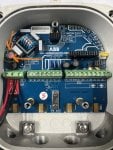
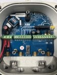
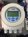
I have ABB water flow meter
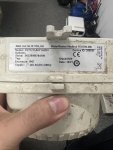
Model : FET1211A0Y1A2M1
We have problem with modbus mainboard
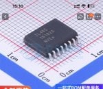
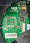
We found ic with 16 pin on this board broken and can’t not reading the name of this IC .
I need to change this but can not find wich IC can replace for this boadr .
Please help me “ dataset “ of this and if i want to change the new IC , we need to know about what ?
Thank you and best regard
Thank for watching and reading
I have ABB water flow meter
Model : FET1211A0Y1A2M1
We have problem with modbus mainboard
We found ic with 16 pin on this board broken and can’t not reading the name of this IC .
I need to change this but can not find wich IC can replace for this boadr .
Please help me “ dataset “ of this and if i want to change the new IC , we need to know about what ?
Thank you and best regard
Attachments
-
 1.5 MB Views: 9
 -
 689.1 KB Views: 10
 -
 1.2 MB Views: 10
 -
 1.8 MB Views: 9
 -
 1.4 MB Views: 7