Checksum error, Insufficient bytes recieved, Timeout - Modbus Poll

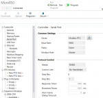
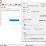
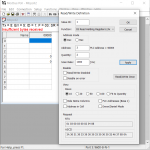
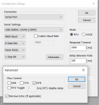
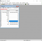
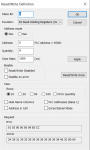
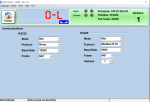
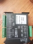
Hello friends, I am trying to establish Modbus RTU485 communication with a weighing device. I'm using ModbusPoll as Master as a test platform (the real one will be a Micro850). I have been able to do this other times, but for some reason I can't do it with this device. I will attach images of the current configurations and the device.
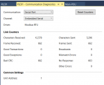
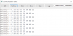
The current error is Checksum error, but it changes depending on the number of addresses I'm trying to read:
-From 1 to 3 is Insufficient bytes received
-From 4 to 9 Checksum Error
->9 Time out
So far I have tried:
-Switch the cables +/-
-Try with different BaudRates
-Different SlaveID
-Different devices of the same model

The same configurations on the master with a device of another Brand/Model work without problem.

I'm really out of ideas. Can anyone help me with this please?
Thanks in advance.
 

Attachments

It seems like there could be noise on the RS-485 lines (possibly from lack of a common ground reference) or perhaps the DAT11 device is constantly transmitting (it's COM2 protocol may be set to continuous or automatic transmission of the weight string, despite you trying to configure the protocol to Modbus RTU).

Have you confirmed that your selection of the protocol to Modbus RTU was successfully written/downloaded to the DAT11? Did you power cycle the DAT11 after changing the protocol?

As for the ground reference, try connecting your USB to RS-485 adapter's ground to pin 3 (S. GND) on the DAT11 (this assumes the RS-232 interface is not isolated from the RS-485 interface).
Thanks for answering.
I connected the GND, but it's still the same.
The DAT11 configurations were downloaded correctly, I was able to check it from the device screen, and I have also power cycle the device.
According to the manual COM1 is for RS232 and COM2 is for 485. I disabled COM1 and COM2 shows configured for ModbusRTU in the device console.
I tried again on the PLC, but the response is basically the same. I've attached images of the settings and responses that I get in the PLC
 

Attachments

Do you have any termination resistors installed or termination enabled on any of the devices (DAT11, PLC, USB to RS-485 adapter, etc.)?

If so, try removing/disabling all termination to see if that resolves the issue.
 
Do you have any termination resistors installed or termination enabled on any of the devices (DAT11, PLC, USB to RS-485 adapter, etc.)?

If so, try removing/disabling all termination to see if that resolves the issue.
None, it's a direct connection
 
I suggest trying the following to confirm proper connections and communication settings.
  1. Set the DAT11's COM2 Protocol to Continuous Transmission so that it will continuously transmit the weight string.
  2. Use a serial terminal emulator, such as PuTTY or Terminal by Bray++, to view the ASCII weight string output by the DAT11.

After you have confirmed successful reception of the weight string, you should have the correct wiring connections and communication settings and can then move back to working on getting Modbus RTU to work.
I have done what you said. And I have the weight data in the terminal. The first 4 numbers are the weight, I don't know what 3E▒2 means.
It is the same wiring that I have been testing ModbusRTU with
 

Attachments

OK, great. That confirms hardware and communication settings. For what it's worth, the packets you're seeing in PuTTY each look similar to this:
▒ 2 -10123D

- Is likely the STX character (0x02h)
2 - is the <status> (a value of 2, i.e. Bit 1 set, means Stable weight)
-1012 - is the weight (net weight, gross weight, or peack value depending on the MODE parameter, prefixed by space characters for padding for a total of 8 characters)
3D - is the <chksum> (the exclusive OR of all characters between the STX and ETX characters

Next, I recommend configuring the DAT11 back to Modbus RTU. But instead of opening Modbus Poll, first open PuTTY again to confirm that there is no output from the DAT11 (a Modbus RTU slave should not transmit anything until it receives a request from the master). After confirming this, close PuTTY and open Modbus Poll. Configure Modbus Poll to read only a single register, such as the Status Register (Holding Register 1).

Also, I don't know if this would make a difference or not, but you may want to try closing the Optimation software on your computer and disconnecting the USB cable from the DAT11 in case that is somehow interfering with the Modbus communication on the DAT11 (since the Optimation software is also serial-port based, just over the USB port).
Okay. Following the recommendations:
-I changed the DAT11 to ModbusRTU and opened Putty, there is no data once the change to RTU is made. So that part is working fine.
-The Optimization software has been offline for a while now. It put the device in Remote mode and I thought it might be causing problems as well.
-I opened the ModbusPoll, generated the connection and when I try to read only one address it gives me a Timeout Error. I suppose it's because all that data is made up of 2 addresses. When I enter 2 addresses it gives me Insufficient bytes received again.

Just to try, would I have to configure the PLC as slave so that it can read the data string in Continuous mode? Or how can I get that data in the PLC?
 

Attachments

-I opened the ModbusPoll, generated the connection and when I try to read only one address it gives me a Timeout Error. I suppose it's because all that data is made up of 2 addresses. When I enter 2 addresses it gives me Insufficient bytes received again.
The Status Register (Holding Register 1) is only 1 address (a single 16-bit register). You should be able to read that register by itself. And although some Modbus slave devices return an error when reading only one register of a two register (i.e. 32-bit) value, many, if not most, do allow this. The different error messages may have something to do with Modbus Poll itself. Do you have any different results using a different Modbus master simulator, such as ModScan or Simply Modbus?

Just to try, would I have to configure the PLC as slave so that it can read the data string in Continuous mode? Or how can I get that data in the PLC?
In theory, you should be able to configure a PLC to receive and decode generic ASCII serial packets. I'm not sure exactly how you would configure your specific PLC, but it would need to be put into a passive receiving mode (this may be called a "slave" mode) and it would need to support decoding the ASCII characters using a format that you program.
 
The Status Register (Holding Register 1) is only 1 address (a single 16-bit register). You should be able to read that register by itself. And although some Modbus slave devices return an error when reading only one register of a two register (i.e. 32-bit) value, many, if not most, do allow this. The different error messages may have something to do with Modbus Poll itself. Do you have any different results using a different Modbus master simulator, such as ModScan or Simply Modbus?
I've tried to read Holding Register 1 by itself and it shows a Timeout Error.
I've tried with ModScan it's the same thing, with one or multiple adresses.
MODBUSscan_1.png

In theory, you should be able to configure a PLC to receive and decode generic ASCII serial packets. I'm not sure exactly how you would configure your specific PLC, but it would need to be put into a passive receiving mode (this may be called a "slave" mode) and it would need to support decoding the ASCII characters using a format that you program.
I'm gonna look into this as well, at least as a backup plan to make this work.
 
What is the USB to RS-485 adapter you're using? From your initial screenshot of Modbus Poll, it shows "USB-SERIAL CH340 (COM3)". I assume this means you're using something based on the CH340 chip.

What does the traffic view (Setup->Display Options->Show Traffic) show in ModScan when requesting 9 registers starting at address 1?
 
What is the USB to RS-485 adapter you're using? From your initial screenshot of Modbus Poll, it shows "USB-SERIAL CH340 (COM3)". I assume this means you're using something based on the CH340 chip.
It's an adapter that was available in my office, it kinda looks like an usb stick. It's worked without problem a lot of times before. Even now I've tried it with another device and works fine.

What does the traffic view (Setup->Display Options->Show Traffic) show in ModScan when requesting 9 registers starting at address 1?
MODSCAN_2.png
If you let it run long enough, some of the numbers changes. But still, not a single valid response
MODSCAN_3.pngMODSCAN_4.png
 
Thank you for the traffic view. That looks quite different from the previous traffic you posted from Modbus Poll.

The traffic view shows that the CRC is indeed incorrect. The last two bytes are the CRC. In the top captures, it shows 5d ff, but the CRC should actually be 5d 01. Similarly some of the bottom captures show 61 ff but should actually be 61 45.

It appears that the last byte is always ff instead of the correct checksum byte. This could very well be a firmware problem in the DAT11. Are you able to get a firmware update from the manufacturer? If not, you may need to contact the manufacturer about this issue.
 
Thank you for the traffic view. That looks quite different from the previous traffic you posted from Modbus Poll.

The traffic view shows that the CRC is indeed incorrect. The last two bytes are the CRC. In the top captures, it shows 5d ff, but the CRC should actually be 5d 01. Similarly some of the bottom captures show 61 ff but should actually be 61 45.

It appears that the last byte is always ff instead of the correct checksum byte. This could very well be a firmware problem in the DAT11.
Would changing some of the settings in the image help with the problem?
MODSCAN_5.png

This could very well be a firmware problem in the DAT11. Are you able to get a firmware update from the manufacturer? If not, you may need to contact the manufacturer about this issue.
I've been trying for the last 3 - 4 bussiness days. I think the person they put me in touch with is more a sales rep, he doesn't give a real technical answer.
 
The hardware flow control is typically for RS-232, not RS-485. There's a small chance it might do something with the CH340 chip, but that's unlikely.

It's also doubtful the timing settings will make any difference. Your timeout is already more than enough at 2 seconds. You could try really slowing down the polls and set the delay between polls to 1000 or even 2000, but again, I doubt it'll make a difference.

When you set the Length to 1 in ModScan, does the traffic view show any response at all (even a partial packet) from the device?

Another thing to try, I've seen devices with firmware bugs that sometimes are only present under certain baud rate and parity combinations. Maybe try different baud rates and parity combinations. A commonly used combination for Modbus is 19200 8E1. It could also be worth trying one of the selections with 2 stop bits, such as 8N2.
 
I noticed it appears you're using an old version of the Optimation software, 1.3.1. The current version is 1.6.6 according to the product's web page. Perhaps the latest version of Optimation includes new firmware for the DAT11, as the manual states the software can be used for updating the instrument firmware.

"Software Optimation 1.6.6" is shown next to "Download" under the green "Ask for a quotation or consulation" button here:
https://www.pavonesistemi.com/weight-transmitters-dat-11
That's the one I'm using. The download file shows v1.6.6
1701116431501.png
There's an option for a firmware update, but it doesn't automatically download the update from the internet. It opens the file browser, so you need to have the file in your computer.
1701116534427.png

When you set the Length to 1 in ModScan, does the traffic view show any response at all (even a partial packet) from the device?
Yes, this is the response I have
1701117059889.png

Another thing to try, I've seen devices with firmware bugs that sometimes are only present under certain baud rate and parity combinations. Maybe try different baud rates and parity combinations. A commonly used combination for Modbus is 19200 8E1. It could also be worth trying one of the selections with 2 stop bits, such as 8N2.
I'm trying the settings you suggested, so far it's the same thing. I'm gonna keep trying some other more methodically.
 
Yeah, it looks like the response for the single register request also has the last byte stuck at ff (it shows 08 ff instead of the correct CRC of 08 45). Strange that both ModScan and Modbus Poll would show timeout errors or insufficient bytes under different scenarios when it's an incorrect CRC all the time.

This really seems to point to a firmware bug. I recommend submitting these traffic capture images to the manufacturer. Hopefully you're able to get in contact with an engineer or proper technical support personnel to resolve it.
Yeah, that's what I'am gonna do .I'm gonna make sure to update here when I get this working.
I'm really gratefull for your help and taking all this time to respond, you're amazing.
 
Top