GCV LVDT drifting

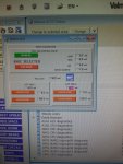
I am troubleshooting the GCV position alarm on a GE Frame 5 with a Valmet DNA control system(relatively new turbine control in power generation space).
The challenge is that after calibrating the 96GC2, the feedback continues to drift until the alarm annunciates again. I have changes the Servo valve and filter on the hydraulic line, but the issue still persists. What can be the cause of the drifting? Is it possible the LVDT is faulty?
 

Attachments

Hi
As this is Valmet DNA CONTROLS systems ( more applicated to DCS usually...)

Can you tell us which procedure are you using ...to achieve correct operation...in order to get that LVDT feedbcak correct..

Are you sure about 65GC operation ...and servo regulator configuration/setting..

According to your statement it is ok for 96GC1 ...BUT not for 96GC2 can you confirm...

I never used that Valmet control system yet so need to get more datas for advising on any thing to do ...


Looking to hear back from you soon..
 
cheedee,

Yet another company wants to prove that almost any programmable controller can be used to control and protect a GE- design heavy duty gas turbine.

How is the LVDT connected to the control system? Directly? Does the control system provide the excitation for the LVDT AND also directly accepts the differential voltage input (output from the LVDT)? Because LVDTs are not commonly used by many companies for position feedback, so many control system manufacturers don’t typically have direct input methods. So control system integrators almost always use converters that connect to the LVDT and output a 4-20 mA signal that most control systems can easily accept. So, we need to know how the LVDT is connected to the control system, and that may drive the troubleshooting recommendation.

As noted above, if the f the snack from 96GC-1 is not drifting, then it’s unlikely that the problemis The servo valve (but, as we know, everyone’s second step for troubleshooting issues with GE-design heavy duty gas turbines is to change the servo…). Have you tried monitoring the actual valve position with a stable reference signal to see if it (the valve) is moving when it shouldn’t? Because if it is moving but the signal from 96GC-1 isn’t changing, then maybe the problem isn’t with 96GC-2….

What is the zero stroke voltage of the two LVDTs—AND what is the excitation voltage?

Is the excitation voltage of both 96GC LVDTs stable as the valve moves?

But, we need to understand how the LVDTs are powered and how their output is connected to the control system. If it’s via converters, and the valve is not moving with a stable reference and one LVDT signal is also stable but the other one is not that suggests the converter, doesn’t it?

Lastly, are you sure the care rod of the LVDT is firmly being held in place and can’t move except when the valve moves? And that the LVDT output is linear over the stroke (travel) of the valve? (Remember, the zero stroke voltage has to be set such that the LVDT is linear throughout the entire stroke (travel) of the valve (bottom end and top end).)

Several things to check. And that we need to know to be of much more help.

Was the gas valve assembly worked on or replaced during the outage to replace the control system?

Finally, if the LVDT is old and hasn’t been replaced in a long time then it could be bad; worn armature windings because the core rod has been rubbing them).
 
cheedee,

So, this is what happens when one responds to Control.com messages with a mobile phone and doesn't take the time to properly proofread the response, and then doesn't check the message before the 'Edit' option disappears....

" As noted above, if the f the snack from 96GC-1 is not drifting, then it’s unlikely that the problemis The servo valve ...." should have read:

As noted above, if the feedback from 96GC-1 is not drifting, then it's unlikely the problem is the servo valve ...."

Sorry for any confusion.

LVDTs have a linear range and two (yes, two) non-linear ranges--the non-linear ranges are at the ends of travel. SO, that means to get to and operate in the linear range of travel two things have to happen. First, the "zero stroke" position of the LVDT movable core has to be adjusted so that when the device the LVDT is attached to is at the minimum ("zero") position the LVDT output is in the linear range. If not, when the device moves to the minimum position it will enter the non-linear output range of the LVDT.

Second, the LVDT must be chosen such that the LVDT output at the maximum position of the device the LVDT is attached to does not cause the LVDT output to be in the other non-linear range.

To satisfy the second requirement, GE chooses LVDTs for applications such that when the output is linear the minimum and maximum positions of the device the LVDT is attached to will not cause the LVDT to go outside of the linear range. BUT, to achieve this it is necessary to adjust the LVDT movable core such that when the device is at its minimum position (in GE-speak, that's called the zero stroke position) the LVDT output is at a voltage that ensures it is not in the lower non-linear range, and then when the device moves to the maximum position the output will also not be in the non-linear range (because GE properly chose the LVDT for the device).

GE has a specification that says the output of the LVDTs (NOT RVDTs (Rotary Variable Differential Transducers)--LVDTs (Linear Variable Differential Transducers)) they buy for GE-design heavy duty gas turbines should be linear between 0.580 VAC RMS and 3.70 VAC RMS for various different stroke lengths, when the LVDT excitation voltage source is approximately 7.00 VAC RMS. THEN, they adjust the LVDT such that when the device it is attached to is as its minimum stroke (0%, sometimes even slightly negative (less than 0%)) the LVDT output will be approximately 0.700 VAC RMS, +- 0.02 VAC RMS (so between 0.680 VAC RMS and 0.720 VAC RMS). The LVDT they choose will then not exceed 3.50 VAC RMS when the device is at its maximum position (100% or sometimes slightly more than 100%). So, when the device the LVDT is attached is anywhere between its minimum and maximum positions the output will be linear. (NOTE: That DOES NOT mean the output will always be 3.50 VAC RMS at the maximum stroke--it simply means the output WILL NOT EXCEED 3.50 VAC RMS at maximum position. A VERY IMPORTANT distinction which most people do not understand.)

So, when the GCV is fully closed, the output of the LVDT should be adjusted by changing the position of the movable core (loosening the jam nuts and turning the core rod) such that the output voltage of the LVDT is NOT LESS THAN 0.680 VAC RMS and NOT MORE THAN 0.720 VAC RMS. The jam nuts of the LVDT should be tightened at this point and the LVDT voltage should be checked to ensure it remained between 0.680 VAC RMS and 0.720 VAC RMS.

In your case, then you want to slowly move the GCV (using the servo valve) to observe the output voltage of the LVDT. The device should change position smoothly and the LVDT output voltage should change slowly and linearly with position as the GCV opens and closes. The output should NOT exceed approximately 3.50 VAC RMS, thought it might not reach 3.50 VAC RMS (and it's perfectly fine if it does not reach 3.50 VAC RMS--it should just never go above 3.50 VAC RMS.) If the GCV moves smoothly but the LVDT output voltage doesn't change smoothly and linearly as the GCV moves, then something is amiss with the LVDT and/or the wiring and/or the input channel to the control system.

It's as simple as that. The LVDT "zero stroke" voltage has to be properly set and then the output voltage will be in the LVDT's linear range throughout the stroke (travel) of the device the LVDT is attached to. If the zero stroke voltage is LESS THAN 0.68 VAC RMS (which is a LOT more than GE's minimum of 0.580 VAC RMS, by the way) there's a chance the output will be non-linear at the minimum device position (not very likely, but still a possibility). If the zero stroke voltage is MORE THAN 0.720 VAC RMS there's a chance the LVDT output will be non-linear at the maximum device position (greater than 3.70 VAC RMS).

So, adjusting the zero-stroke voltage to between 0.680 VAC RMS and 0.720 VAC RMS is important and necessary. And once that's done, the LVDT output should be linear as the device moves throughout it's entire range of travel. If the device moves smoothly when being moved (stroked, in GE-speak) but the LVDT output does not change smoothly and linearly with device position, then there's something wrong with the LVDT or the wiring between the LVDT and the control system or the input channel of the control system the LVDT is connected to.

LVDTs are very simple devices--as long as one understands they have to be adjusted properly to ensure the output will be linear over the stroke (travel) of the device they are attached to. GE does that--as long as the LVDT zero stroke voltage is properly adjusted/set and verified, if necessary. Nothing more, and nothing less.

GE chose to use LVDTs for several reasons. First, they are non-contact devices--meaning that when properly installed no part of the LVDT touches any other part of the LVDT. Second, they are very resistant to the effects of vibration (presuming the bolts used to mount them are tight and don't loosen, and the jam nuts on the movable core are properly tightened). Third, they are very good in high temperature applications (such as in the turbine compartment where the IGV actuator is usually located and where it can get very hot). But, MOST IMPORTANTLY: They DO NOT drift over time. They either work, or they don't, but the output does not drift over time. They rarely require adjustment or "calibration." They aren't "active" electronic devices; they are passive electronic devices in that they don't have chips or amplifiers or the like; they are just transformers whose output changes as the movable core changes position. Very simple, elegant little devices.

The calibration (feedback scaling) should be checked and verified periodically, but if proper records are kept the records will most likely show that over time the calibration is pretty darn rock-solid and rarely, if ever, under normal operating circumstances, requires adjustment or "calibration." LVDTs are commonly used for aircraft applications (like wing flap positions, and aileron positions, and such). And, the reason is--they are vibration (and temperature) resistant AND the output rarely drifts over time. They are also used on rocket engines--lots of vibration and LOTs of heat (and cold!). And, the output rarely drifts.

Hope this helps! And we hope to hear back from you on how you resolve this problem!!!
 
Hi
As this is Valmet DNA CONTROLS systems ( more applicated to DCS usually...)

Can you tell us which procedure are you using ...to achieve correct operation...in order to get that LVDT feedbcak correct..

Are you sure about 65GC operation ...and servo regulator configuration/setting.. Yes. Its ok

According to your statement it is ok for 96GC1 ...BUT not for 96GC2 can you confirm... Yes 96GC2 is faulty

I never used that Valmet control system yet so need to get more datas for advising on any thing to do ...


Looking to hear back from you soon..
 
Top