Facebook
 Google
 GitHub
 Linkedin
Hello team,
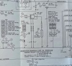
Onsite we have GE LM6000 Gas Turbine Generators and the Generator (Brush) & Gearbox Lube Oil System uses a mist oil extraction system to vent the GLO tank / system.
This mist oil extraction uses a single fan arrangement that also has a cooler and hepa filtration system.
We can adjust the fan air flow which in turn raises or lowers the tank vent pressure.
The system has a GLO tank pressure alarm set at -25mm/water.
With new filters installed and the air flow flap at 100% open, we can achieve a max pressure of approx -120mm/water.
My question is, does anyone know of the desired GLO tank system pressure?
Our GE manuals only reference the alarm value.
The risk is with the air flap set wide open, we have increased air flow, dragging excess oil mist, blocking the filters quickly, with a rapid decline in GLO tank pressure.
With the air flap closed, we run the risk of system oil leaks around shaft seals etc and hitting the alarm set point.
Attachments
-
 458.3 KB Views: 26