This was the question posed to the OP that generated the response about "substituted signals:"
"... Did GE add the new T/C inlet temperature sensors, or did they just substitute the signals from existing T/C inlet temperature sensors (in place of the RTD inlet temperature sensors) to start/stop the evaporative coolers?"
I was asking because I had a hunch this might have happened--that the ctifn T/C signals were being used for the evap cooler start/stop instead of the RTD readings upstream of the turbine inlet air filters. (We are dealing with GE Belfort here.... ) And, honestly, I'm not sure exactly what the response means, or if my question was fully understood.
But, I'll admit I'm still confused about everything else. And, as you say, there are lots and lots of questions. Like why it is thought that changing the location of the air temperature sensing for the evap cooler start/stop would be a positive thing. (I have a suspicion that one or two of the units were using different air temp sensors than the other units for the evap cooler start/stop and someone felt the power output of those units was "higher" than the others and so felt the switch (substitution) would be good for all the units--but that's just a SWAG.)
We would welcome any help with focusing in and trying to get to the bottom of this. It's intriguing, but that makes three of us who are unsure about this thread.
Dear Irfan, GOOD MORNING, it seems we are working opposite each other, I live in California and so it is the start of my day, and near the end of your day. This does assume you are working a day shift, and not a night shift at this time anyway.
I think maybe I am understanding your questions and statements, hopefully. I will offer a little more background just for the sake of understanding.
As I understand it not all GE designed heavy frame gas turbines are supplied with inlet evaporative cooling. Also not all machines have the three temperature sensors ATID in the inlet filter house. Evaporative cooling only works well in areas where the ambient humidity is low, and the ambient temperature must be high enough for water to evaporate and cool the incoming air. The two units I maintain have evap coolers that work well in the summer when our ambient temperatures can range from 80 degf to 110 degf. During the winter we drain the coolers as our temperatures can drop to ~30 degf where the water could freeze.
In climates that have high ambient temperatures, but also have high humidity, I typically see inlet cooling systems that use mechanical compressors and refrigerant to cool the inlet air. This type of system uses a lot of energy, but when prices for electricity are high it makes it economical to run the inlet chillers to increase unit output.
In your case it sounds like you run your machines at full load most, if not all the time. This is when the machine is most efficient and when inlet cooling can also increase the output most effectively. Not all plants operate like this. My plant has to follow load, so we are not always at full output.
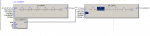
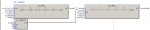
I have attached snips of logic for 3 different GE 7EA machines. They are a smaller machine as compared to your 9E, but similar enough to compare for the sake of logic. The signal L4ACRUN is the signal that generally turns on the evap cooler pump. Two of the logic snips use the signal ATID to enable the evap coolers along with a temperature switch signal L26ACN. You will notice one site has ATID set to be above 80 degf or 26.6 degC to enable the cooler pump. Another site uses the same signal, but ambient temperature only has to be above 73 degf or 22.7 degC. The last logic snip does not use ATID but only uses the signal L26ACN. This is a temperature switch device typically located in the inlet before the evap media. In the device summary I have the setpoint is 56 degf or 13.3 degC for this switch. My point is logic for control of the evap coolers is not consistent from site to site. It would be interesting to see logic for your evap coolers to see what GE Belfort has been doing. Having logic consistent from site to site, machine to machine is good for a troubleshooting process. But it is also possible that exceptions can be made for individual customers and sites that best fit the generation mix for that customer, as long as the machine is still protected.
In your case it sounds like your site has been working with GE to change logic to allow the evap coolers to run more consistently in the months when ambient temperatures are high enough. I believe that logic for the evap coolers turns them off to protect the machine from possible water condensing back into droplets of water at the machine inlet that could damage compressor blades. Because of the large drop in pressure at the inlet bellmouth, inlet air that is saturated with water could condense back to droplets if the inlet temperature is low enough.
Does this information help?
Any possibility you can post any images of your logic?
It is good as an operator that you are monitoring your machines. This is where having multiple machines can be helpful for comparing unit operating conditions. I don't think you can expect each machine to operate the same as another, but you can compare each one and try to determine if something is wrong or something is different.
I have one comment regarding the 40 MW shortfall. If I understand correctly, the 24-hour shift report recorded a loss of 40 MW. Divide 40 MW by 24 hours and one arrives at an average loss of 1.67 MW per hour. And, was this 40 MW shortfall versus the previous 24 hours, or 24 hours one week ago, or one month ago or one year ago?
MIKEVI has outlined the basics of inlet cooling very well. I want to add that even though evaporative coolers are thought to be "self-regulating"--which means the amount of evaporation is controlled by the ambient temperature and humidity--that DOES NOT mean that the water flows down the media can be adjusted once at the beginning of the hot months and never checked again. Nor does it mean the water flows can be checked once a week and adjusted and expect them to work properly. "Working properly" for evap coolers means the entire evap cooler media is wet (meaning there are no dry areas on the media), there is sufficient flow to wash away residue on the media (from dust and contaminants in the air) and the water flow is not so high that droplets of water are pulled off the media by the air flow causing puddling of water on the floor of the inlet filter structure downstream of the evap cooler. I have even such high "carryover" (the term for water droplets pulled off the media by air flow) that air flow drew the water which had collected on the floor into the inlet plenum where a lot of it entered the bellmouth and what didn't pooled in the bottom of the inlet forming a small pond. Evap coolers are not "set it and forget it" devices like most people think they are; as ambient conditions change over the hot months, or even daily periods, the water flows down the media need to be visually checked and adjusted as necessary. Insufficient water flows on the evap cooler media cause dry areas ("streaks"), and the wet areas around the fringes of the streaks can get covered with dried dirt and airborne contaminants that don't get properly washed down the media and into the trough at the bottom--which also has to be checked periodically to ensure the level of dirt doesn't get too high.
Dry streaks also mean that insufficient evaporation is occurring--which means the efficiency of the evaporative cooling process is not as high as it could or should be.
Evaporative coolers seem like such simple equipment, but they're really not, and because of the very large air flows across them they really require at least twice daily visual inspections (or video cameras to observe the media). And, even though the air is usually filtered before it flows across the evap cooler media, filters DO NOT remove all dust and contaminants--which are easily captured by the water flowing down the media and be dried on the media if the water flows are not sufficient to prevent streaks. And, dirty media, even when wet, just don't have a high efficiency of evaporation.
Anyway, as MIKEVI says, the on/off setpoints of evap coolers can vary from site to site and are often based on recommendations from the cooler manufacturer--which may or may not take site conditions at particular sites into consideration. And, most manufacturers are going to try to "encourage" as much usage of the evap cooler system as possible to be perceived as having the most efficient cooler system or contributing greatly to the increased output of the unit when the evap cooler is in operation. BUT, achieving the highest output is not a "set it and forget it" task with evap coolers--to achieve the best operation and the highest output increase they really need very close attention. And, keeping the media clean improves the life of the media (before it has to be replaced).
I want to suggest that we start talking about each unit specifically, instead of saying "one unit ran continuously" or similar. If Unit 3 ran continuously, we need to know if unit 3 is liquid fuel-fired or gas fuel-fired. And we need to know specifically what signals (from which sensors) are used to enable and disable (turn on and turn off) the evap cooler of each unit. It seems you are not familiar with ToolboxST to be able to get that information yourself, and have to rely on the I&C tech's for answers. That's going to make this process take longer, but I'm just getting more and more confused with each response. So, let's build a table for the six units and start filling in the requested data and go from there.
I also want to propose using a table (worksheet) to start keeping track of the information for each unit, to help understand what unit uses which fuel, and so on; like this:
I have attached the file which can be used for capturing the data, and then re-attached after edits by incrementing the revision number of the file (so Iaq_WS0.xlsx would become IaqWS1.xlsx after the first edit, and Iaq_WS2 after the second edit, and so forth. I'm sure we will add some rows for additional information, but we need a place to keep track of this information. Snippets can be added to posts, also.
Other (constructive) comments and/or suggestions are welcome.
Dear CSA,
You know I am not working in west like, I am working east side.
I am pilot of turbine for several years means control room operator but now shift team leader.
But sadly truth I know very well how to use tool box but here management decide operation haven't access for toolbox and all HMI on operator mode,so I not have an access till went to morning shift and inform control personal for open tool box for checking this. Even 1.5 month machine generate less production I&C not followup any machine behviour for this new logic implementation.
I found this issue and report my manager because manager operation told me for followup why production is less and give me task for analyze.
I already Inform operation manager, he calculate efficiency of gas turbine as Compare all units and current conclusion they decided to downgrade software to old settings of CTIM but not immediately after MOE allows.
Dear CSA, this first finding about less MW production by my manager because he followup all calculations.
As you know liquid fuel operate turbines have water injection aslo and always MW for 24 hours always more then other gas operated turbines.
You know after HGPI all stuff inside turbine new all seals new, but suspecious MW on 24 hours 35 to 40 less but before this signal substitution all going.
I compare all reports before and after HGPI yes must be LDO machine
production is more but now reverse production is less
Wonderful job of explaining how to determine turbine performance and the troubleshooting of the same.
It is sad that you explained it to each other. The original poster and his manager will continue to place data in a spreadsheet without knowledge of what TTRF1, CTIM, etc, etc. ARE.
I miss my Mark I controls of yesteryear, where everything is a given. No hidden logic.
Just hanging on.....New Year and New expectations
Yes late reply due to apposite time zone and working in shifts, thanks for your support, now return for night shift .
tonight answer related block images so on .
Dear CSA ,
thanks for share spread sheet for follow-up , tonight i shall try to respond all your question related this tread.
i have one control related question as a operation personal without knowing logic block.
if we force this CTIM VALUE for 1 hour , change dynamic to constant value and give same temperature value of thermocouple which was before its safe for just one hour.
as you know for logic setting I&C again need to degrade software and install old one and this we need unit stand still position. means off unit for more then 30 hours.
now already ambient is low 5degc and no any evaporative cooler machine on baseload , we took live value of CTIF-1A and CTIF-2A and then average value we can put as a force value in the place of rtd_ctif3r place for observing that effects on MW production or no? we shall do just for analyze.
CSA is this good way or directly shutdown machine after standstill degrade old software.
First, the language/translation issue is making it difficult (for me, at least) to understand most of the technical information you are trying to convey.
Second, you seem to have this idea that we know or should know all the differences of the six machines at your site because you know the differences and you're trying to explain them to us. We're not there alongside you and you have to understand that we're not there alongside you and when we're dealing with multiple units from half way around the world and the details are changing--and are unclear (because of the language issue, also) we can't be of much help. Unless you are willing to put the information in a form we can easily refer to.
I'm going to offer up this one final observation and then I'm going to follow Curious_One's lead and not get any further involved in this thread. It's a rabbit whole of unknown depth and it's not going to lead to a good conclusion in this thread.
Most industrial control systems that use T/C's employ a concept called cold junction temperature compensation. You can use your preferred World Wide Web search engine to learn why it's necessary. The Mark* uses it also; it's mentioned in manual GEH-6721 in the section on T/C I/O Packs and terminal boards. I'm offering this information because it's a possible explanation which should be investigated if for no other reason than to eliminate it as a possible cause of the issue which is being discussed in this thread.
I once worked at a site with two Mark* control panels (actually located in the same room just a couple of metres apart). One of the panels was exhibiting some very odd--and intermittent--behaviours which were preventing reliable operation (at unusual times), AND the power output of this particular unit would ”drift” throughout the day slowly going up and down, seemingly randomly. The air conditioning outlets for the room were in the ceiling, and one of them was directly above the panel which was having the problems. It was found that when cold air from the vent directly above the panel with the issues was blowing into the vents of the panel it was altering the cold junction compensation temperatures of two of the three control processors in the Mark*--which was causing the T/C temperature readings to fluctuate (as the air conditioner started and stopped) by as much as 6-12 deg F. This was causing the Mark* to think the exhaust temperature and the compressor inlet temperature and the compressor discharge temperature were all going up and down, which was causing the Mark* to change fuel flow-rate and fail to transition combustion modes at times and just behave erratically.
A piece of cardboard was taped in place to cover the louvers at the top of the Mark* to block the direct flow of cold air from the air conditioner vent into the Mark*. Immediately the unit output started to settle into a more constant range and over the next few days as the unit was started and stopped the problems with combustion mode transfers stopped.
I AM NOT saying this is exactly what is happening at your site. What I AM saying is that it's entirely possible that something is causing the cold junction compensation in the Mark* control panels to be causing the temperature difference you are seeing and trying to report and trying to associate with the power output deviation you are trying to describe.
I can tell you further that GE does not not follow its own engineering recommendations for mounting Mark VIe I/O Packs to prevent heat from adjacent I/O Packs from affecting nearby I/O Packs. (Anyone reading this who doubts how much heat Mark VIe I/O Packs can generate just needs to put their hand above a PDIO I/O Pack at the bottom of a vertical column of PDIO I/O Packs and then move their hand slowly up that column to the top to see how much warmer it is near the top than the bottom. Do the same with the combined analog I/O Packs/terminal board combinations (I believe they are called TCATs).)
That's one possible explanation for the temperature differences you are trying to describe--presuming there are no other physical differences between the unit's we can't be aware of.
ToolboxST can be used to check the cold junction compensation temperatures of each I/O Pack, in each Mark VIe panel.
Also, T/C wiring is ”finicky.” If the wiring between the actual T/C and the Mark* is not correct all along the circuit, then there can be small errors introduced such as you are trying to describe. (Some I&C Tech's will argue that T/C's are simple two-wire devices and the individual terminations are NOT important--but you want to avoid those I&C tech's because they don't know what they are doing.) It's a simple matter to make these checks in a couple of junction boxes and in the Mark* to eliminate this as a possible cause.
Troubleshooting is often a process of elimination--especially for unusual and/or intermittent problems.
Best of luck. I wish I could help, but to do so I would have to be there on site, and that's not going to happen.
[As an aside, I have been in several similar situations before, where a ”problem” was assigned to a new or junior employee by a supervisor or manager who just didn't want to deal with the ”problem” or wanted the new/junior employee to just go away. In every case, the problem turned out to be more significant than first believed. In every case but one, the supervisor/manager jumped in and took complete credit for the troubleshooting and resolution, completely ignoring the efforts of the new/junior employee. That's life, eh? In this case, it sounds like you have a lot of procedures and possibly some biases to overcome, and you need to get multiple groups to work together to gather data, and be involved in a process of elimination--which some people object to. They don't offer any help or input but they're sure what you're suggesting is not the answer.]
If they're not contributing to the solution, they are contributing to the problem.
CSA,
Although this is not a contribution to this thread. I was involved with a steam process plant in the early 90's. The steam turbine feed pumps were replaced with electric motor driven feed pumps to "save a ton of money". A short electrical outage caused a lot of problems for those poor boilers expecting water.
A LOT OF Management folks arrived at the powerhouse due to a production shutdown after the loss of steam pressure. The electrical foreman waltzed in and simply said "If you are not part of the solution then you are part of the problem....Please leave."
I notice you are tip-toeing around the edges of this thread.... I would really like to help the original poster, but the language barrier and the scattered nature of the replies without trying to put the information in a more understandable format is just too difficult. And, I firmly believe this is kind of a fishing expedition--if not for the original poster, then for his supervisor/manager who told him to investigate this.
I also believe the original poster is not very well versed in understanding signal names and functionality--AND he's further hampered by the practices of the site which prevent operations personnel from accessing ToolboxST and Trend Recorder.
But, it's just not going to be possible this time. And, sometimes I just have to accept that and move on. Perhaps if someone more knowledgeable were there at site alongside the original poster and was given access to ToolboxST and whatever historical data they have (it sounds like they have some good historical data) it would be possible to more quickly and easily get to the bottom of this.
I have been to too many sites where talent and ambition are squandered--literally. And egos and politics run the plant instead of logic and reasoning. And, there are even sites where there is some combination of the two that most often work together to achieve the common goal of reliability and production. But, there are also sites where well-meaining individuals went too far in trying to "improve" operations they really didn't understand and caused some harm--which leads to some of the protections alluded to in this thread, also. We don't know what the full situation is, but whatever it is is probably difficult for several people at the site, if not more.
Anyway, I don't understand why you would want to work on a Mark I--not at all. Especially a Mark I EHC steam turbine control system. Uggghhh! I am a huge fan of Trend Recorder and wish more sites would learn to use it--and use it! It's just so powerful and has so many bells and whistles and yet it's so much simpler than something like OSIsoft PI. It's not the easiest tool and it could stand a few improvements (like being able to run it without having to open ToolboxST, and being able to run it on a PC without ControlST/WorkstationST/ToolboxST installed on it), but given what it can do and how helpful it can be it's just a waste of a good application at so many sites around the world.
 Facebook
 Google
 GitHub
 Linkedin