Facebook
 Google
 GitHub
 Linkedin
Today I have an EM24 and an SDM120 so part of an Openhab system where I can see A, V, W etc.
I want to change ID and Baud as I am currently using 2 Serial for Usb key, and want to assemble this.
SDM120 current: id = 1, baud = 2400, stopBits = "1.0", parity = "none", dataBits = 8, encoding = "rtu"]
Em24 current: id = 2, baud = 9600, stopBits = "1.0", parity = "none", dataBits = 8, encoding = "rtu"
I want
EM24 = id = 1, baud = 9600, stopBits = "1.0", parity = "none", dataBits = 8, encoding = "rtu"
SDM = id = 2, baud = 9600, stopBits = "1.0", parity = "none", dataBits = 8, encoding = "rtu"]
In addition, I have an EM23 that I do not know the connection to yet.
I want
EM23 = id = 3, baud = 9600, stopBits = "1.0", parity = "none", dataBits = 8, encoding = "rtu"
I tried in the program Modbus Poll without success.
So I hope someone can guide me
Attachments
-
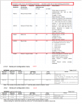 186.1 KB Views: 12