Is there some of firewall in your windows system trying to protect something?
Maybe try with an old windows 7 (or XP) system while not connected to internet.
I think you may be using the Modbus Poll software incorrectly. Your Communications Traffic from post #18 seems to show Modbus RTU packets because it includes a CRC at the end "C2 AD" (but for some reason without the address byte of 33 at the beginning). You may be trying to connect via serial port instead of Ethernet, since a timeout error is typically associated with Modbus RTU (serial connection) not Ethernet.
Also, your Communications Traffic from post #20 don't seem like valid Modbus requests at all.
As a first step, I suggest downloading the latest version of Modbus Poll, if you haven't done so already.
Next, follow these steps to connect to the MC 750 using Modbus Poll.
1. Open Modbus Poll
2. Click Setup->Read/Write Definition...
3. Enter 33 for the Slave ID, Check the PLC Addresses (Base 1) option, Enter 101 for the Address, Enter 4 for the Quantity as shown here:
4. Click Connection->Connect...
5. Select Modbus TCP/IP for the Connection, Enter the IP address of the MC 750 under Remote Modbus Server IP Address, Click OK
If the above still doesn't work and you continue to see Timeout errors, try changing the Slave ID setting in Modbus Poll to 1 or 0.
I carefully read the suggestions as you kindly replied me, and followed them in details.
1. I downloaded the newest "Modbus Poll" software for version 9.4.4 build 1457 for 64 bit.
2. Before launched newly installed software, i stuck cable headers into the ports, energised the MC 750, and launched console ping action:
2. Then I launched the new "Modbus Poll" and input fields:
3. Then I started up with the connection:
4. Then I tried to enable connection:
5. I also tried with entring Device ID = 1 and 0. Please have a look at:
The result did not change.
Today I also tried with disabled Internet connection, assuming it may affect Modbus connection performance.
The Connection Failed error you're receiving means that your computer could not establish a TCP connection with the MC 750 on port 502. Therefore, changing the Slave ID will have no effect, because you are not even getting far enough for Modbus Poll to send a request to the MC 750.
This may be due to a misconfiguration on the MC 750 such that Modbus/TCP or port 502 is disabled or perhaps the MC 750 got into a bad state and its Modbus driver crashed. The manual does state that if a connection is made to the user defined port (TCP port 10001), that all other connections (including connection to port 502) are disabled. Try power cycling the MC 750 and see if you can establish a connection.
Another possibility is this may be a firewall issue, as @patrickduis mentioned, where your computer's firewall is blocking port 502. Try disabling your firewall or add an exception for Modbus Poll and/or TCP port 502.
I recommend that you try using Iskra's own software to connect to the MC 750. If you are unable to successfully do this, Iskra's technical support should hopefully be able to assist you.
After you are able to get Iskra's MiQen software communicating Modbus/TCP to the MC 750, then you should be able to communicate using any other software, including Modbus Poll and your own software.
Yesterday morning happened something strange to the Modbus TCP IP connection, which was successfully maintained all day long yesterday.
When I energised MC 750, and tried to re- establish Modbus TCP-IP communication, it failed to open. But some minutes afterwards with the same software the Modbus UDP-IP connection's been established. Please have a look at the picture below:
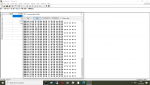
Although the device ID's been set to 33(hex 21) in the communication traffic table it is changing its value from 21 to 01 and so on. But when I deenergised the MC 750 the stings in the communications traffic table continued to run! And "No coonnection" message has not been launched by the software!
On the rear of MC 750 the leds been blinking frequently when Modbus TCP IP communication was active. But now they blink only few seconds within it's been energised.
Are there any means(an IT softwares) to diagnose connections problems as network adaptor failure on the device, unstable connection in the cable headers, etc? To understand what possible events may lead to Modbus TCP IP connection lost?
I just wanted to provide some clarification on this.
You are seeing this because you connected using "Modbus UDP/IP". UDP is connectionless, meaning Modbus Poll does not establish a connection to the MC 750, but rather simply sends UDP packets to the MC 750's IP address. However, the MC 750 does not support Modbus UDP (most devices don't, as it is not standardized). This is why the communications (TX packets) continues to run even when the MC 750 is powered off. This is also the reason the LEDs on the rear of the MC 750 was only blinking once every second or so because you're Response Timeout in Modbus Poll was set to 1000ms.
You should only use the "Modbus TCP/IP" option to connect to the MC 750.
Note that Modbus UDP is not standardized and is not part of the official Modbus specifications, although some products support it. This thread discusses Modbus UDP in more detail: https://control.com/forums/threads/modbus-udp.10884/
Yes, it seems Modbus Poll is now successfully communicating with your MC 750. However, you have selected "03 Read Holding Registers (4x)" for the Function setting in your Read/Write Definition. You should select "04 Read Input Registers (3x)" since all of the registers documented in the MC 750's user's manual have a 30,000 offset, meaning they are Input Registers. Registers 30101 - 30104 are the "Actual time" according to the register table in the MC 750 manual.
You can try to read other values from the MC 750, such as "Average phase Voltage U~" at registers 30113 - 30114 or "Average Current" at 30136 - 30137. Although, be aware, the MC 750 uses unusual encodings for 32-bit parameters spanning two registers (refer to the "Data types decoding" section on page 173 of the MC 750's manual), so Modbus Poll will not be able to decode the value properly.
I also wanted to point out another observation from your communication traffic above. It seems Modbus Poll is also trying to read Holding Registers 1 - 10 from Unit ID 1 (which I believe is the default Read/Write Definition in Modbus Poll). These are the TX lines that do not have an RX line after them. Do you have another window open in Modbus Poll behind the "Mbpoll MC750-760" window?
Sidebar:
Modbus register numbering and function codes are quite confusing, especially to first-time Modbus users. In Modbus, Holding Registers are also known as 4X references and may be documented with a 40,000 offset (sometimes 400,000 offset) and use function code 03 Read Holding Registers. Input Registers are also known as 3X references and may be documented with a 30,000 offset (sometimes 300,000 offset) and use function code 04 Read Input Registers. For example, the term "Register 30,001" and "Input Register 1" mean the same thing.
To further complicate things, when referring to Modbus registers in this way, 1-based numbering is used (i.e. Input Register 1 is the lowest possible register number). But the register address that gets encoded into the Modbus packet is 0-based (i.e. one less than the register number, i.e. Input Register 1 is encoded as register address 0 in the Modbus packet).
Yes, sometimes the elder version of Modbus Poll is also run with the newer one(only one is connected at a time!). This is why the newer has time limitation of 10 minutes elapsed, it disables connection. This is an 'evaluation mode' that is very awkward in use. The elder is run constantly without time limitations, that's why I use it.
From morning I've been thinking on understanding essence of addressing to input registers on MC's.
Why they are offset to 30000 so that 113 corresponds to 30113 PLC address?
As you kindly defined in your reply, there is a possibility of reading input registers on MC, and which of them corresponds to voltage and current.
Today I tried to collect voltage and current value. And therefore I assembled some wiring on my MC 750. I have connected them as manual says according "1b connection type". One current is flown through CT A hole, and a voltage applied between 11(N)-8(L) pins on the rear . Both adjusted with autotransformer. The MC is fed with +24(pins 13,14) V constant battery voltage.
The measured voltage is set to 0-100 V and current to 0-5000 mA range.
1st and 2nd picture assume voltage reading:
3rd and fourth an 5th assumes current reading:
Are these values(U and I) correctly addressed and collected in the software?
I do not understand value readings in highlighted spaces.
How do they correspond to measured values shown on MC display?
Please re-read my response in post #28 carefully. It answers many of your questions and addresses your confusion.
As I stated, the "Average phase Voltage U~" is at registers 30113 - 30114. This means you need to enter 113 for the Address and 2 for the Quantity (not 1).
Also, as I mentioned, the MC 750 uses a special formatting for the 32-bit values. In order to decode the values, you will need to refer to the "Data types decoding" section on page 173 of the MC 750's manual.
I recommend that you view the values in hexadecimal in Modbus Poll to better help you decode the values. To do this, select Hex - ASCII from the Display menu.
For example, for Average Current (registers 30136 - 30137) you are currently seeing values of 0 and -1280. In hexadecimal, this equates to 0x0000 and 0xFB00. Assuming the MC 750 sends its 16-bit registers with the least-significant value in the first register, this equates to a 32-bit value 0f 0xFB000000.
The Average Current value uses the "T5" data type, which is defined in the MC 750 manual as follows:
bits # 31...24 Decade Exponent (Signed 8 bit)
bits # 23...00 Binary Signed value (24 bit)
Therefore the numbers you're reading are as follows:
bits # 31...24 = 0xFB (-5 decimal)
bits # 23...00 = 0x000000 (0 decimal)
Note that you can use an online hexadecimal to decimal converter to convert the values, such as this: https://www.rapidtables.com/convert/number/hex-to-decimal.html
Enter the hexadecimal number in the "Enter hex number:" box and the decimal value will be shown in the "Decimal from signed 2's complement:" box.
So your value is 0 x 10^-5 or 0.00000.
It's possible the Average Current really is 0 on the MC 750. The parameters you're showing on the display are U1, I1, and P1. You need to read the following registers for these values (as documented in the MC 750's register table):
Voltage U1: Registers 30107 - 30108
Current I1: Registers 30126 - 30127
Real Power P1: Registers 30142 - 30143
Try reading the registers above and decoding the values as I showed in my example above to confirm that they match what the meter displays.
Begging your pardon for having use an elder version of Modbus Poll instead of the newest 9.4.4 version. It doesn't have a possibility of showing data in Hex-ASCII format, but only HEX. How much is the differnce?
Please have look at pictures below:
Dear sir, I have re-read your post #28, and made some conclusions below: However, you have selected "03 Read Holding Registers (4x)" for the Function setting in your Read/Write Definition. You should select "04 Read Input Registers (3x)" since all of the registers documented in the MC 750's user's manual have a 30,000 offset, meaning they are Input Registers. Registers 30101 - 30104 are the "Actual time" according to the register table in the MC 750 manual.
Does it mean that “03 Read Holding Registers (4x) would have a 40000 offset? Does 4x mean 40000 offset and 3x mean 30000 offset?
Input registers I assume means the registers to temporarily(until MC is powered on) bearing input data(voltage, current etc. values )?
Holding registers I assume means the registers to permanently bear(in non volatile memory) the data, these are “Connection Mode”, “CT Secondary” etc, right? You can try to read other values from the MC 750, such as "Average phase Voltage U~" at registers 30113 - 30114 or "Average Current" at 30136 - 30137. Although, be aware, the MC 750 uses unusual encodings for 32-bit parameters spanning two registers (refer to the "Data types decoding" section on page 173 of the MC 750's manual), so Modbus Poll will not be able to decode the value properly.
This I see when T5 data type has two 16 bit registers: one bears decade exponent, and the other register bears mantissa: 10-4 x 1234, right?
To further complicate things, when referring to Modbus registers in this way, 1-based numbering is used (i.e. Input Register 1 is the lowest possible register number). But the register address that gets encoded into the Modbus packet is 0-based (i.e. one less than the register number, i.e. Input Register 1 is encoded as register address 0 in the Modbus packet).
This I get like there is the other type of registers, not “Input Registers” and “Holding Registers” which has an offset equal to 1. So that the 1st register refers to 0.
Also the 3rd register refers to 2nd. And this is called 1-based numbering. Is this reasoning correct?
First off, let me just say that the MC 750 is one of the most difficult Modbus devices to work with due to its unusual data formats, so I applaud your patience and perseverance in working with this device as an introduction to Modbus.
It appears that you are correctly reading the voltage, current, and power. However, you are not correctly decoding the values. It seems the online hexadecimal converter does not support 24-bit values, so you must enter 32-bit values. For the Voltage U1, you were entering a 16-bit value, so the converter thought the value was negative when it is not.
For example, here is how to decode the Voltage U1.
30107 = 0xA178
30108 = 0xFD00
This equates to a 32-bit value of 0xFD00A178.
bits # 31...24 = 0xFD (-3 decimal)
bits # 23...00 = 0x00A178 (41336 decimal) (Enter 0x0000A178 into the online hexadecimal to decimal converter)
41336 x 10^-3 = 41.336
Here is how to decode the Real Power P1.
Here are the values you're reading
30142 = 0x0409
30143 = 0xFDFF
This equates to a 32-bit value of 0xFDFF0409.
bits # 31...24 = 0xFD (-3 decimal)
bits # 23...00 = 0xFF0409 (-64503 decimal) (Enter 0xFFFF0409 into the online hexadecimal to decimal converter)
-64503 x 10^-3 = -64.503
Note that I had to "sign extend" the 24-bit values of 0x00A178 and 0xFF0409 above to 32-bit values of 0x0000A178 and 0xFFFF0409, respectively, when typing it into the online hexadecimal to decimal converter, since the converter does not support 24-bit values. The rule for sign extending is if the most-significant bit is 1, you prepend 0xFF. If the most-significant bit is 0, you prepend 0x00. In other words, if the first 2 hexadecimal digits are greater than or equal to 0x80 then you prepend 0xFF to the value (i.e. 0xFF0409 is equivalent to 0xFFFF0409), otherwise you prepend 0x00 (i.e. 0x00A178 is equivalent to 0x0000A178).
Begging your pardon for having use an elder version of Modbus Poll instead of the newest 9.4.4 version. It doesn't have a possibility of showing data in Hex-ASCII format, but only HEX. How much is the differnce?
Input registers I assume means the registers to temporarily(until MC is powered on) bearing input data(voltage, current etc. values )?
Holding registers I assume means the registers to permanently bear(in non volatile memory) the data, these are “Connection Mode”, “CT Secondary” etc, right?
This I get like there is the other type of registers, not “Input Registers” and “Holding Registers” which has an offset equal to 1. So that the 1st register refers to 0.
Also the 3rd register refers to 2nd. And this is called 1-based numbering. Is this reasoning correct?
The 0-based numbering versus 1-based is just a convention that Modbus uses. The register address that gets encoded into the packet is 0-based (i.e. 1 less than the 1-based register number).
For example, this is how to decode the request and response to Read Input Registers 30113 - 30114 to device 33.
Dear gentlemen,
I sincirely thank you for the valuable advice and help, without I hardly began to study this difficuilt device. May the Lord bless you, may success and good luck be with you!
This time I tried to read and decode to decimal Real, Reactive, Apparent Power flown throug MC750.
Please have a look at pictures below:
P1, registers 30142-30143, T6
30142 = 0xD6AA
30143 = 0xFEFF
This equates to a 32-bit value 0xFEFFD6AA
bits # 31..24 = 0xFE (-2 decimal)
bits # 23..00 = 0xFFD6AA - since the first 2 hexadecimal digits are greater than 0x80, I prepend 0xFF to the value, so
0xFFD6AA is equivalent to 0xFFFFD6AA :
0xFFFFD6AA = -10582
P1 = -10582 x 10^-2 = -105.82 W.
---------------------------------------------------------------------------------------------
The Reactive Power refers to registers: 30150 = 0xFE53
30151 = 0xFEFF
This equates to a 32-bit value of 0xFEFFFE53.
bits # 31..24 = 0xFE (-2 decimal)
bits # 23..00 = 0xFFFE53, since the first 2 hexadecimal digits are greater than 0x80 then I prepend 0xFF to the value, so
0xFFFE is equivalent to 0xFFFFFE53 , which is -429 decimal, and therefore:
Q1= -429 x 10^-2 = -4.29 Var.
-----------------------------------------------------------------------------------------
The Apparent Power refers to registers: 30158 = 0x2848
30159 = 0xFE00
This equates to a 32-bit value of 0xFE002848.
bits #31..24 = 0xFE (-2 decimal)
bits #23..00 = 0x002848, since the first hexadecimal digits are less than 0x80, I prepend 0x00, and therefore
0x002848 is equivalent to 0x00002848
which is 10312 decimal, so our S1 value is:
S1= 10312 x 10^-2 = 103.12 VA.
Great! Your calculations look correct to me. You should be able to confirm the values using the meter's display.
Your next step is to try this with your homebrewed software. You can enter one of the TX packet's shown in Modbus Poll (one that has the 21 unit ID, not the 01 unit ID) in your software and you should get a response from the meter.
Yes, the values of Active Power P1 and Voltage U1 on the display match the values read and decoded to decimal in Modbus Poll.
This rule you have taught me is very useful, I have to make decodings many times.
--------------------
After I started with my software, and since local IP inside Winsock control of VB.net is fixed(I cannot change it) I changed ethernet adaptor IP from 192.168.0.1 to 192.168.1.14 and MC750 IP from 192.168.0.2 to 192.168.1.12 .
I tried to do the same things to my software, and these are screnshots, please have a look at them below:
I beg your apologise for not having told you of being used port 10001 instead of 502. This MiQen software shows that it is being used for Modbus RTU protocol in this specific case, please have a look on it in the right upper corner of MiQen software window. These port number misunderstandings prevented us from expiriencing Modbus protocol itself, so I decided to input port number as in the MiQen case, and this instantly led to connection succeed with Modbus Poll.
Please kindly write me your conclusions and advices on this situation.
You should only enter the Modbus packet into your software. In your images, you've also included Modbus Poll's packet ID and TX indication.
For example, instead of entering:
003007-TX:0A CF 00 00 00 06 21 04 00 9D 00 02
You need to enter:
0A CF 00 00 00 06 21 04 00 9D 00 02
Regarding port 10001 versus 502, I can't answer this. You would need to contact Iskra technical support for an explanation on why you are unable to connect using port 502. TCP port 502 is reserved for Modbus/TCP communications, so all devices that support Modbus/TCP must be able to support port 502.
If you are able to connect and read values using Modbus Poll, you should be able to connect and receive responses using your own software (you may need to make sure Modbus Poll is disconnected from the meter before connecting with your software, though).
Good morning, dear sir!
Yesterday afternoon and today morning I have been wondering on how can Modbus Poll manage to extract valuable data from Mc750 but my software could not.
Based on your valuable advice and reason I came up with a plan for further work on homebrewed software:
1. I've been adviced implicitly(please have a look at screnshot below) on forum not to use 'Winsock' control in my software. As VB.NET like other programming languages of .NET uses 'Namespace' paradigm, it is beside of purpose use legacy(after VB6) 'Winsock', when 'System.Net.Sockets' namespace methods are available.
2. Since Modbus Poll is enabled to extract valuable data from MC750, and my software could only get the same string input before, there is some difference in packet exchange maybe. That could be probably caught by Wireshark.
3. I captured MC750---ModbusPoll and MC750---"My software" packet exchange, and think how analyze them.
4. After having caught differences on wireshark(if happens so) let's analyze them and making some conclusions on how homebrewed software should operate.
5. Seeing the difference and making right conclusions could enable me to design the correct software probably capable of extracting valuable data from MC750-760 input registers.
Please have a look at the archive which contains wireshark logs.
It appears the Wireshark captures are only of Modbus Poll, is this correct? Are you able to capture packets of your software sending transmissions to the MC 750?
As a general recommendation, I suggest you look into using an existing .NET Modbus library for your software, such as the following, for example: http://easymodbustcp.net/en/
Good afternoon, dear sir!
To answer your question definately, I launched wireshark again, then launched my software, established connection, then send/received a transmissions to MC750 many times, then terminated connection, stopped wireshark capture, and then saved it as: "homebrewed software only.pcapng"(please see in zip-archive). I also launched again wireshark to capture modbus poll packets, please have a look at: "modbus poll only.pcapng" capture file.
Is connection being established by "homebrewed software" proper connection?
Yes, thank you sincere I follow this link and your recomendations!
It appears the Wireshark captures are only of Modbus Poll, is this correct? Are you able to capture packets of your software sending transmissions to the MC 750?
As a general recommendation, I suggest you look into using an existing .NET Modbus library for your software, such as the following, for example: http://easymodbustcp.net/en/
 Facebook
 Google
 GitHub
 Linkedin