How calculate combustion spread

Hi dear all,
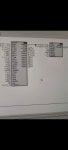
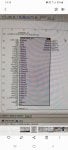
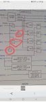
I am interested to know, what is the equation or formula of allowable spread for GT, what signals should I use to calculate it, in attachment I give the photo of spread monitor
 
V. ACTUAL SPREADS
Three spreads are calculated from the exhaust thermocouple readings:
SPREAD #1 (TTXSP1)--The difference between the highest and the lowest thermocouple reading;
SPREAD #2 (TTXSP2)--The difference between the highest and the 2nd lowest thermocouple reading;
and,
SPREAD #3 (TTXSP3)--The difference between the highest and the 3rd lowest thermocouple readings.

VI. ALLOWABLE SPREAD
The allowable spread is the sum of two values: a nominal allowable spread and a bias.
The nominal allowable spread is the steady state spread limit. It varies, typically, between 30 and 125 degrees
F as a function of average exhaust temperature and compressor discharge temperature.
The bias is an adder to the nominal allowable spread which accounts for the temporary increase in actual
spreads that occur during transient operational periods. It is a temperature value which varies between 0 and,
typically, 200 degrees F.
During steady state operation, the bias value is 0 degrees F. When a transient operational condition occurs,
such as a rapid change in load, the bias value steps to 200 degrees F. It remains at that value until, typically,
2 minutes after the transient condition ends. Its value then decays exponentially to 0 degrees F on a 2 minute
time constant. Refer to Figure 6.
The transient conditions which cause the bias to step to 200 degrees F are: 1) fuel transfer, 2) turbine startup
and shutdown, 3) load changes produced by a governor RAISE or LOWER signal, and 4) load changes produced
by a rapid change in FSR.
 
ControlEng999,

The topic of combustion monitoring has been discussed many times before on Control.com, and past threads can be found using the Search feature of Control.com. Also, there is a list of 'Similar Threads' at the bottom of every thread which can be very helpful, too.

To begin your understanding of combustion monitoring and how exhaust temperature spreads (allowable and actual) are determined you need to right-click on the blocks you have posted while looking at them in Toolbox/ToolboxST and then select 'Item Help' or 'Block Help' to receive the pictorial, relay ladder diagram representation of what's happening inside the blocks.

I'm going to give you some hints. TTXSPV4 stands for Turbine Temperature-Exhaust Spread, Version 4.

The spread calculator uses ALL of the exhaust T/Cs when it is enabled--it does not reject ANY exhaust T/Cs (as is widely and falsely believed).

The allowable exhaust temperature spread calculation uses the axial compressor discharge temperature T/Cs in its determination of the allowable spread.

The exhaust T/C values are sorted into two arrays--first from highest exhaust temperature value to lowest exhaust temperature value, and second from highest exhaust temperature value to lowest exhast temperature value by location. (As an example, if 564 deg C was the highest exhaust temperature value, and 549 deg C was the second lowest exhaust T/C value and 523 was the third lowest exhaust T/C value, and they were at physical exhaust T/C locations 6, 7 and 11, the first three values of the temperature array would be 564, 549 and 523, and the first three values of the location array would be 6, 7, and 11.

The highest and lowest exhaust T/C values and the highest and second lowest and the highest and third lowest are then subtracted from each other to determine TTXSP1, TTXSP2 and TTXSP3.

And, the physical locations of the highest and lowest values are comparted to each to determine if any of them are adjacent (next to) each other. These all drive the logic signals L60SP1, L60SP2, L60SP3, L60SP4, L60SP5 and L60SP6.

From there, the logic signals go to a block of rungs that check for magnitude of differential and adjacency--and if those conditions are satisfied the various alarm and trip conditions are annunciate and actions taken (such as alarming and tripping).

THE ABOVE DESCRIPTION IS FOR THE BASIC FUNCTIONALITY OF TTXSPV4--NOT FOR ANY OTHER VERSION OF THE EXHAUST TEMPERATURE SPREAD BLOCK. THE EXACT, PRECISE DETAILS OF WHAT MAGNITUDES AND WHAT ADJACENCY CONDITIONS CAN RESULT IN ALARMS AND TRIPS ARE SPECIFIC TO EACH AND EVERY MACHINE--AND MUST BE DETERMINED BY USING THE RELEVANT CONTROL CONSTANT VALUES AND UNDERSTANDING THE RUNGS WHICH DO THE CHECKING AND ALARMING AND TRIPPING. FULL STOP. PERIOD.

Without being able to see the application code running in the machine being discussed it is impossible to say what spreads will result in alarming or tripping.

What it IS POSSIBLE to say is this: If the Mark* is a TMR system using TTXSPV4 if two exhaust T/Cs are failed (reading low) and a third exhaust T/C also fails--the turbine is going to trip (this is presuming all three redundant control processors are healthy, communicating and participating in controlling and protecting the turbine and auxiliaries). This is probably the BIGGEST question I get: How many failed exhaust T/Cs can exist before the turbine will trip--and WHY???

The (false) statement that always accompanies the question is, "The Mark rejects the highest- and lowest exhaust T/C values--so why is it tripping on them?!!?!?!!!??" The average exhaust temperature calculation, TTXM, does do just that--it rejects the highest and the lowest exhaust T/C values, as well as any values less than a certain temperature (usually 500 deg F) when calculating the average exhaust temperature (TTXM). BUT, when checking for combustion trouble, the Mark* MUST use ALL exhaust temperatures because a really high value(s) or a really low value(s) may be caused by a true combustion problem which will damage the turbine--possibly catastrophically. So, no T/Cs are rejected or ignored when detecting combustion trouble by determining exhaust temperature spreads.

Learning to read and understand the graphics used in describing how some of the algorithmic blocks used in the application code of a Mark* is important. Critically important if you DO NOT want to fall prey to falsehoods, wives' tales myths and incorrect tribal knowledge about Mark* turbine control operation and function. It's all there for anyone to read and see and document for themselves--and the best part is: It's exactly what's running in the machine being troubleshot; it's not hearsay or incorrect written documentation, or incomplete written documentation. It's NOT difficult to learn--but it does take practice, and it's best to have a copy of what you're trying to learn to make notes (in pencil) on to help with your edification. I can't stress this enough--having your own copies of P&IDs and rungs you're trying to understand to write on, use a highlighter on, make notes on--if you think you can do it without your own personal copies and without making notes--you're wrong. (There are one or three people I have know who were smart enough and had photographic memories who did it without personal copies and making notes/highlighting/etc.--but they were the exception and not the rule. I was not one of them.... Though I have committed most basic (non-GE Belfort) P&IDs and rungs to memory, it's only because I have looked at them repeatedly over nearly 40 years and have seen them in my sleep...!)

Anyway, if you have more questions, we'll try to answer. There are really two parts to the combustion monitor (spread detection): the algorithm, and the rungs which use the L60SPn outputs of the algorithm to annunciate alarms and perform the tripping.

There should be NO doubts about what was written above. You may have questions, but not doubts. You may want more precise information--but you're going to have provide more detail about the situation (including actual data from Trend Recorder!) as well as screen captures of the Item/Block help and Control Constant values. And, I would prefer if you worked out how you think it should work and tell us and then we correct you--if necessary. "A person who is given a fish will eat for a day; a person who is taught how to fish (or learns how to fish!) will eat for life."

Hope this helps!
Glad to see you back in action, full of detail and it looks like more patient ?? Is this a sign of maturing years !!
 
ControlEng999,

Please try explaining the issue you are having with TTXSPL. Is this happening right after a maintenance outage, or after a trip from load? What's going on? What fuel is the unit burning? If the unit is dual fuel (gas/distillate) have you tried running on the other fuel? If so, what happens to the exhaust temperature spreads?

If you can give us data (time-based values) it would REALLY help us to understand what's going on.

If you're just trying to explain the block functionality or "justify" it to someone--the TTXSPL part is difficult. Very difficult.

Personally, as much as I have tried calculating TTXSPL using what's in the algorithm (TTXSPV4) I have never been able to make my calculation match what the block comes up with. Never. This is one of those FBM calculations (Friggin' Black Magic)--and there are only a couple of them in the GE-design heavy duty gas turbine block library (not counting MBC/ARES blocks (Model-Base Control/Adaptive Real-time Engine Simulation)).

If you have high exhaust temperature spreads (at or over approximately 100 deg F (approximately 40 deg C)) the problem is NOT the value of TTXSPL--as much as anyone wants to believe it is. If the values of the exhaust temperature spreads are close to the value of TTXSPL and are setting values of L60SPn to logic "1"s then it's pretty likely there's some kind of combustion problem.

Unless your Axial Compressor Discharge Temperature T/C inputs are grossly in error, then the problem might be the value of TTXSPL.

I have seen units with one really high exhaust T/C value and one or two failed (low) exhaust T/C values and a couple of lower than expected exhaust T/C values have really "distorted" TTXM values which can cause distorted fuel flow-rates. Which can make exhaust temperature spreads worse.
No, everything is fine, but I would like to be ready and able to calculate and compare the value of spread, because we are going to do first fire on gas fuel. "If you're just trying to explain the block functionality or "justify" it to someone--the TTXSPL part is difficult. Very difficult" it means that formula of calculation doesn't work???
TTXSPL = TTKSPL4* TTXM - TTKSPL3*CTDA + TTKSPL5
 
ControlEng999,

I don’t have access to Mark VI/VIe application code at this writing. Have you looked at the Item- or Block Help to see how TTXSPL is calculated in the TTXSPV4 block in the application code in the turbine at your site?

Can you post a screenshot of the TTXSPL calculation portion of the Item- or Block Help for TTXSPV4? (It’s usually at the top of the block.)

The TTHA and TTHL stuff in later posts to the thread you cited are, I believe, used in a different version of TTXSPVn block.

And, I’ve never seen the COMB_MON_6FA block you posted a screenshot of before.

Did you try the calculation for expected values of TTXM and CTDA—say for 500 deg C TTXM and maybe 400 deg C for CTDA using the Control Constant values from the application code in the Mark VIe at your site? If so, what value did you arrive at?
 
No, everything is fine, but I would like to be ready and able to calculate and compare the value of spread, because we are going to do first fire on gas fuel. "If you're just trying to explain the block functionality or "justify" it to someone--the TTXSPL part is difficult. Very difficult" it means that formula of calculation doesn't work???
TTXSPL = TTKSPL4* TTXM - TTKSPL3*CTDA + TTKSPL5
1618835200383.png1618835200383.png
 
ControlEng999,

I don’t have access to Mark VI/VIe application code at this writing. Have you looked at the Item- or Block Help to see how TTXSPL is calculated in the TTXSPV4 block in the application code in the turbine at your site?

Can you post a screenshot of the TTXSPL calculation portion of the Item- or Block Help for TTXSPV4? (It’s usually at the top of the block.)

The TTHA and TTHL stuff in later posts to the thread you cited are, I believe, used in a different version of TTXSPVn block.

And, I’ve never seen the COMB_MON_6FA block you posted a screenshot of before.

Did you try the calculation for expected values of TTXM and CTDA—say for 500 deg C TTXM and maybe 400 deg C for CTDA using the Control Constant values from the application code in the Mark VIe at your site? If so, what value did you arrive at?
Yeah CSA, I can attach these screenshots, I would like to get comments and help from you, if it is possible, because I can't understand these scheme, and result of my calculation is not the same like live value ttxspl and etc.
 

Attachments

What part of “I (CSA) have never been successful in reliably calculating TTXSPL to match the value on the display” is so difficult to understand?

And, what is the concern about first fire on gas fuel that is driving this need to be able to calculate TTXSPL?

As long as the gas fuel piping from the connection at the inlet to the gas fuel stop valv(s) all the way to the fuel nozzles in the combustors is clean and free of debris (rocks and gravel, cigarette butts, weld rod and weld slag, rags, scarf, etc.) and liquids (natural gas liquids, gas compressor lubricating oil, diesel, gasoline, water, condensation, etc.) the likelihood of high exhaust temperature spreads which might exceed TTXSPL are very low. Whether this is a machine that has been running on other fuels or a brand new machine.

And being able to verify the calculation of TTXSPL isn’t going to solve any spread problem.
Now, having said this, provide the values of the relevant Control Constants and the variable values you have been using for CTDA inputs and TTXM as well as the corresponding TTXSPL values calculated by the Mark* that you are unable to match with your calculation and we can try to help you understand what the problem might be.

If the machine is not running and you are trying to use actual values of TTXM and CTDA (at ambient temperature)—well, there are permissive and clamps (minimum and maximum limits) in the block which are going to skew the calculation, especially if the unit is not running.

The formula you are so desperately trying to use is a HIGHLY simplified version of what is in the screenshots you provided. But, as was said, there are other permissive and clamps. And if the machine is running there are are conditions which can cause the values of TTXSPL to jump up to a maximum limit and to ramp back down to the calculated value over time (as has been quoted in the snippets attached to this thread in other responses).

I can—and do—sympathize with your desire to be able to verify the values of TTXSPL calculated by the Mark* at any point in time. But I, personally, have never been able to reliably do that. I have created spreadsheets to do that “quickly” and hopefully more reliably than my feeble manual attempts at using a calculator, but I’ve never been able to successfully and reliably duplicate what the Mark* produces.And that’s okay, because if there are high exhaust temperature spreads (over approximately 40–50 deg C)—AND the hottest and coldest values are adjacent to each other—then the problem isn’t the calculation of TTXSPL!!! (Which can be adversely affected by highly inaccurate values of CTD and failed exhaust T/Cs—as has been written in this thread.)

People always want to blame the Mark* for exhaust temperature spread problems, but it’s so highly unlikely that it rarely happens, and never in my career (of almost 40 years).

Finish providing the required information (Control Constants), and tell us what values of CTD and TTXM you are using and what the results of your calculations are and what the Mark* is calculating and we can try to get some resolution for you.

Other than that, we are speculating.
The GT was not running, and as result i think my calculation is not correct, i would like to wait for first start up and take these constants for calculation, and after that i will go back here and discuss my result, however could you share your spreadsheet for calculation TTXSPL?
 
The GT was not running, and as result i think my calculation is not correct, i would like to wait for first start up and take these constants for calculation, and after that i will go back here and discuss my result, however could you share your spreadsheet for calculation TTXSPL?
I reckon this subject has been beaten to death :-
1) If you know your machine well and trend and record the Exhaust Temp. / Spread Limit and Actual Spread, you should be able to spot increasing spreads, analyze them and make the changes required to correct them (change Fuel Nozzles / change Exhaust T/C)
2) I know it maybe interesting to be able to calculate TTXSPL accurately but I don't see that it really has much relevance to correcting actual machine spread problems. Since the introduction of Spread Monitoring in MKV and, in its early days, the large fluctuations in TTXSPL due to load changes, I reckon that knowledge of how actual Spread problems look on Exhaust Temps should give you enough knowledge to fix them before they cause damage.
For me, in 45+ years, I have only had one case where rising spreads caused damage, and part of that was by misuse of Logic Forcing to influence trips.
It all generally comes back to knowing your machines performance, both from a maintenance & operational perspective.
Maybe this subject should be moved to a more specific subject of how to calculate TTXSPL as that is where it seems to be going.
 
Glenmorangie,

With 45+ years of experience you must know that the subject of exhaust temperature spread calculation is a herd of horses that just won't die--no matter how long they are beaten and tortured. They don't even expire due to old age.

This thread IS about how to calculate exhaust temperature spread, and ControlEng999 is right--from the first snippets he provided, the values of CTDA1 and -2 are negative, implying they are disconnected or not working.... (see the values (in green) for A_CTD_SL; they are both negative). The unit is not running--OR the CTD T/Cs are not connected or missing or ...?

I am unable to clearly read the values of several of the TTKSPn Control Constants.

ControlEng99 just wants a quick and easy way of confirming the value of TTXSPL--for whatever reason. It's clear he doesn't understand that if the actual exhaust temperature spread values are significantly disparate and the highest and lowest exhaust T/C values are close to each other that if the unit is experiencing Combustion Trouble Alarms and/or Trips the problem is not the calculated value of TTXSPL.

Some prior experience has likely formed his opinion and his dogged decision to want to accurately--and easily--be able to confirm/verify the calculated value of TTXSPL and its importance to preventing alarms/trips. And, he's not willing to share the reasoning or experience; he just wants to be told how to easily and accurately calculate/verify the Mark* value of TTXSPL.

I'm really torn about this. The spreadsheets I tried to create were done in hotels 20 years ago. They're long gone; and they're not coming back.

I think one of the problems I'm having here is that I think there are problems with the Item/Block Help file for TTXSPV4.

1618973732077.png

The two red circles are each missing a value.

1618972489248.png

In two red circles above in the snippet above I'm unable to clearly see the engineering unit values; I think it's 'nd' for 'non-demoninational,' but I intensely dislike guessing (always have).

In the lower of the two snippets above, the value of signal name L83SPO (which is being passed to block value L83SPO) is 'False'--which means that in the upper snippet above the missing value in the upper red circle is being passed to the summing junction (which is out of the snippet)--which means the value being passed to TTXSPO (also signal name TTXSPO) IS NOT being passed to the summing junction (out of the snippet).

In the lower of the two snippets above, the value of L83SPMB is 'True'--which means the missing value in the lower of the two red circles is being passed to the A input of the block to the right. And because L83SPMB is 'True' that also means the output of the block (marked with a red 'C') is being passed to the summing junction to the right--and it's ALSO being passed to the BIAS output of the block (which is the signal name TTXSPLB--making the lower missing value 0).

TTXSPL of 52 deg C is the result of the addition of TTKSPL8 and the value being passed to KSPL7 (some SELECT block output; see the top of the lower snippet), which is the minimum CLAMP value for CTD, so it makes CTD equal to 38 deg C. Now, the value of TTKSPL8 gets passed to the summing junction for ttxspl_z1 and the output of the prior summing junction (which is TTKSPL8 minus 0)--making TTXSPL equal to 14 (the value of TTKSPL8) plus 38 (the value of the output of the CTD clamp block (because both CTD values are LESS THAN the minimum value, which is KSPL7, which is the output of some unseen SELECT block: 38).

I will clean this all up later. But, in this example, the value of TTXSPL is confirmed to be 52 deg C. It's NOT the highly simplified equation/formula the original poster wanted, but it works (in this example).

So, now, if the original poster (ControlEng999) wants to tell us what value he calculated, we might be able to tell him where his mistake was.

But, I'm going back to my previous statements: When the unit is running, confirming TTXSPL is damn near impossible to do. And, also--it has NOTHING WHATSOEVER to do with solving or understanding exhaust temperature spread issues. (Again, unless, there is someting grossly wrong with CTD and/or TTXM (like two failed exhaust T/Cs).

Nada.

Zilch.

Zero.

Zippo.

Niente.
 
Glenmorangie,

With 45+ years of experience you must know that the subject of exhaust temperature spread calculation is a herd of horses that just won't die--no matter how long they are beaten and tortured. They don't even expire due to old age.

This thread IS about how to calculate exhaust temperature spread, and ControlEng999 is right--from the first snippets he provided, the values of CTDA1 and -2 are negative, implying they are disconnected or not working.... (see the values (in green) for A_CTD_SL; they are both negative). The unit is not running--OR the CTD T/Cs are not connected or missing or ...?

I am unable to clearly read the values of several of the TTKSPn Control Constants.

ControlEng99 just wants a quick and easy way of confirming the value of TTXSPL--for whatever reason. It's clear he doesn't understand that if the actual exhaust temperature spread values are significantly disparate and the highest and lowest exhaust T/C values are close to each other that if the unit is experiencing Combustion Trouble Alarms and/or Trips the problem is not the calculated value of TTXSPL.

Some prior experience has likely formed his opinion and his dogged decision to want to accurately--and easily--be able to confirm/verify the calculated value of TTXSPL and its importance to preventing alarms/trips. And, he's not willing to share the reasoning or experience; he just wants to be told how to easily and accurately calculate/verify the Mark* value of TTXSPL.

I'm really torn about this. The spreadsheets I tried to create were done in hotels 20 years ago. They're long gone; and they're not coming back.

I think one of the problems I'm having here is that I think there are problems with the Item/Block Help file for TTXSPV4.

View attachment 1192

The two red circles are each missing a value.

View attachment 1191

In two red circles above in the snippet above I'm unable to clearly see the engineering unit values; I think it's 'nd' for 'non-demoninational,' but I intensely dislike guessing (always have).

In the lower of the two snippets above, the value of signal name L83SPO (which is being passed to block value L83SPO) is 'False'--which means that in the upper snippet above the missing value in the upper red circle is being passed to the summing junction (which is out of the snippet)--which means the value being passed to TTXSPO (also signal name TTXSPO) IS NOT being passed to the summing junction (out of the snippet).

In the lower of the two snippets above, the value of L83SPMB is 'True'--which means the missing value in the lower of the two red circles is being passed to the A input of the block to the right. And because L83SPMB is 'True' that also means the output of the block (marked with a red 'C') is being passed to the summing junction to the right--and it's ALSO being passed to the BIAS output of the block (which is the signal name TTXSPLB--making the lower missing value 0).

TTXSPL of 52 deg C is the result of the addition of TTKSPL8 and the value being passed to KSPL7 (some SELECT block output; see the top of the lower snippet), which is the minimum CLAMP value for CTD, so it makes CTD equal to 38 deg C. Now, the value of TTKSPL8 gets passed to the summing junction for ttxspl_z1 and the output of the prior summing junction (which is TTKSPL8 minus 0)--making TTXSPL equal to 14 (the value of TTKSPL8) plus 38 (the value of the output of the CTD clamp block (because both CTD values are LESS THAN the minimum value, which is KSPL7, which is the output of some unseen SELECT block: 38).

I will clean this all up later. But, in this example, the value of TTXSPL is confirmed to be 52 deg C. It's NOT the highly simplified equation/formula the original poster wanted, but it works (in this example).

So, now, if the original poster (ControlEng999) wants to tell us what value he calculated, we might be able to tell him where his mistake was.

But, I'm going back to my previous statements: When the unit is running, confirming TTXSPL is damn near impossible to do. And, also--it has NOTHING WHATSOEVER to do with solving or understanding exhaust temperature spread issues. (Again, unless, there is someting grossly wrong with CTD and/or TTXM (like two failed exhaust T/Cs).

Nada.

Zilch.

Zero.

Zippo.

Niente.
Great thanks CSA, I appreciate it, I don’t want to seem stupid and dull, could you tell me, what is on the picture, I highlighted it and what is the ttxspl_z1?
 

Attachments

ControlEng999,

The squares with 'X' in them are Multiplication blocks. In the uppermost red circle, the Control Constant TTXSP1 would be multiplied by ttxspl_z1 (the multiplicand is connected to the top of the Multiplication block, and the multiplier is connected to the left side of the Multiplication block and the result of the multiplication of ttxspl_z1 and TTXSP1 is connected to the right side of the block and feeds the 'B' input to the COMParator block). MOST blocks are designed to read left to right--with inputs on the left and outputs on the right; sometimes the area available for drawing the element dictates a slight change to the locations of all inputs,

But now you're going "below" TTXSPL--and this thread is about TTXSPL.... ttxspl_z1 is calculated above the reference in the snippet you sent (in the TTXSPL area of TTXSPV4). Usually when you see signal names in lower-case inside a block it means that the signal is internal to the block and is calculated elsewhere in the block--or the signal is to be used somewhere else inside the block where it is being calculated. And, usually the signal name suffix _z1 means the value of the signal on the previous scan of the block or function.

ttxspl_z1 is the usually the value of TTXSPL from the previous scan of TTXSPV4 during the execution of one frame of the application code (usually at a 25 Hz scan rate (40 milliseconds).

The only stupid question is the one that doesn't get asked. (There are good times--and better times--to ask a question, and there are poor times--and bad times--to ask a question, also.) And, there really isn't such a thing as dumb question--just dumb answers. I'm sure you think our answer "... TTXSPL has nothing to do with solving exhaust temperature spread problem....", but if one is calculating exhaust temperature spreads and allowable spread limits because of a problem with excessive exhaust temperature spreads (in an effort to prove the exhaust temperature is not real and is a fake exhaust temperature spread, falsely determined by the Mark*), then one's efforts are misdirected. That's all we are saying: If the Mark* is annunciating combustion trouble alarms and/or trips and there are clearly cold (or hot) spots in the gas turbine exhaust, trying to prove the alarming/tripping is being erroneously caused by the Mark* is not the solution.

If you're "first-firing" a turbine on gaseous fuel ("first fire" to me means the first time a unit is operated, could be during commissioning or after a maintenance outage), there are LOTS of things to be watching for. Including fuel leaks in the turbine compartment. If this piping is all new and the fuel nozzles were newly installed then there should have been great care taken with cleanliness during assembly. BUT, there will probably be conical ("witches' hat") strainers installed in piping flanges just to catch and debris which didn't get removed prior to assembly. IF something beyond the strainers and blocks the fuel nozzle passages that's going to be reflected in high exhaust temperature spreads. The hard thing about gaseous fuels is determining which combustor/nozzle has the problem--it's much more difficult than with liquid fuel. But, it will show up in the exhaust temperature readings.

Use Trender/Trend Recorder to capture values you want to review later. You can capture all the exhaust T/C values; TTMX; TTXSPL; CTD values; all the things that go into the combustion monitor and spread detection. You can monitor speed, CPD, FSRs, all of these things. And you can capture them at a 40 msec rate, and you can then share the information with others, too. (All the Process- and Diagnostic Alarms are captured (by default--unless someone turned of the default settings!), too!) So, it's very beneficial--VERY beneficial. Especially during first-firing (or re-starting after any outage). It's an indispensable software tool which is rarely used but can be so powerful--and it's relatively easy. Just takes practice--and it doesn't require any passwords which would result in unintentional changes to application code or Constants--it really is pretty robust and innocuous, and valuable. I sincerely wish more people would use it--but....

Anyway, hope this helps! I think we're getting there. I have some more documentation work to do on this topic, but we're close.

Don't get too far "down in the weeds"--a colloquialism which means, don't concentrate so much on the minutiae and details you forget what the task is (to solve exhaust temperature spread problems--not to anticipate them, or try to prove the Mark* wrong (or right!). The task is to solve exhaust temperature spread problems. The Mark* is rarely wrong. Unless the Control Constant values are horribly in error (which is possible--but not likely with factory default values), or the inputs are bad (such as bad CTD inputs and/or failed exhaust T/Cs). If there's "garbage" coming into the determination, then the determination will be "garbage," too.

I would REALLY like to understand why you are so fixated on this aspect of "first-firing" on gas fuel. It's probably a task someone assigned to you--and that's often a bad sign.... But, if this is something you are suspecting to be a problem during "first-firing" on gas fuel, I would really like to understand what your concern(s) is(are). I learn A LOT from posting to--and reading feedback--from Control.com. It helps me to better formulate responses in the future. (My responses can always be better--even technically!). So, if you would, please, help me to understand your concern(s).

Hope this helps!
 
Hi All


As CSA stated there are missing values in the red circles ....I dont know about your unit configuration ...type /frame..
But for a Frame 6B as built FILES the value is zero/0...

Can you provide also Control Constants specification sheet of this unit...

After had read various posts here on this thread... I come with these questions

Looks like also there may be a recheck to do with TTKSPL8 VALUE at 14°C Usually between frame 6B & 9E value is from 92 to 111 °C...
And check TTKSPL9 SETTED AT 10 SEC ...100SEC FOR A FRAME6B can you confirm these values...


Looks you will need to confirm first the constants values prior to calculate anything on this unit ...

ControlsGuy25
 
Top