IGV, Servos and LVDT

Hello team,
I am trying to calibrate the IGV on GE Frame 5, but the difference between the manual values I input and the actual IGV position is much and difference gets bigger as I try to move the IGV to fully open i.e from (45-85 Deg)
Manual Setpoint: 45
Actual Reading on machine:45

Manual Setpoint: 65
Actual Reading on machine:50

Manual Setpoint: 85
Actual Reading on machine:55

Manual Setpoint: 105
Actual Reading on machine: 70

Manual Setpoint: 130(displays 128 on the autocal)
Actual Reading on machine:85

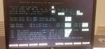
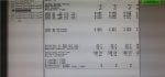
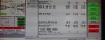
This is a rough description of the readings. The unit has been down for a while(approx 1 year) and we just finished a HGPI on it, to the best of my knowledge the IGV was operating fine. We have 80bar of Hydraulic pressure, the servo was replaced (Moog), the IGV blades have been cleaned. Please what else can be done? , also what is the ideal servo current and LVDT voltage (not sure if this is phrased properly) , I have uploaded the autocal screen?


1) Type of Mark* being used = Mark V(TMR)
2) Did you perform a servo current polarity check after replacing the servo and before starting this "calibration" procedure?=Yes
3) Have you been changing the Null Bias Current value when you have been "calibrating" the IGVs?=NO
4) What is the Null Bias Current value presently running in the Mark* right now?= ?? How can I measure this??

And one more thing:

5) What are the values of the LVDT voltages when the IGVs are fully closed (somewhere around 45 DGA, or slightly less)? 34DGA
LVDT 1 voltage- <R> -0.306 , <S> -0.315 ,<T> -0.302
LVDT 2 voltage- <R> -0.277 , <S> -0.275 ,<T> -0.277
 

Attachments

cheedee,

That's just a HORRIBLE screen shot--not the quality of the photo (it's okay), but the data on the AutoCalibrate display!!!

2) Did you have the IGV servo powered by each individual processor when checking the servo current polarities?

4) You don't measure Null Bias Current; it's something that's set in the I/O Configurator, on the TCQA screen for the respective servo valve output regulator (Number 5 in your case).

5) I'm surprised about those LVDT voltages and the angle you listed (34 DGA).

Anyway, when the IGVs are "fully closed" (which they should be when L20TV-1 is logic "0" AND the Aux. L.O. Pump and Aux. Hyd. Pump are both running, and the Manual feature of the IGV AutoCalibrate screen is NOT being used, the LVDT voltages should each be approximately 0.680 VAC RMS to 0.720 VAC RMS (or, 0.700 VAC RMS, +/-0.020 VAC RMS). That is, when the LVDT actuator has moved the IGVs to the position where they can not close any further (some kind of mechanical limit--be it the actuator or a ring stop), the IGV LVDT feedback voltage should be approximately 0.700 VAC RMS (and it can ONLY be properly measured with a True AC RMS voltmeter/multimeter). The voltages shown on the AutoCalibrate display are AC RMS values. On the photo you provided, the manual reference was 128.0, and the IGV feedback calibration is basically indicating 124 (the median of the three readings on the row labeled "Actual Position").

USUALLY, when the IGVs are "fully closed" and against some kind of mechanical limit, or mechanical stop, the measured angle (using a machinist's protractor) is LESS THAN 34 DGA, something around 30-32 DGA or so. 34 DGA is the minimum operating angle--and one doesn't want the unit up against a mechanical limit/stop when it is supposed to be controlling a particular angle, so the mechanical limit/stop is set to be slightly less than 34 DGA, usually two degrees or so less than the minimum operating angle).

USUALLY, when the IGVs are "fully opened" and against some kind of mechanical limit, or mechanical stop, the measured angle (using a machinist's protractor) is MORE THAN 84 DGA, something around 85-87 DGA or so. 84 DGA is the maximum operating angle--and one doesn't want the unit up against a mechanical limit/stop when it is supposed to be controlling a particular angle, so the mechanical limit/stop is set to be slightly more than 84 DGA, usually two degrees or so more than the maximum operating angle).

So, it would appear that the IGV LVDTs may not be properly configured to begin a calibration--with the fully closed voltages set to approximately 0.700 VAC RMS.

When calibrating IGV LVDT feedback using AutoCalibrate, one needs to know the ACTUAL, MEASURED angle of the IGVs when they are at the fully closed mechanical limit/stop, AND when they are at the fully open mechanical stop/limit. And, that value has to be entered into a file named ACALIB.DAT, in the proper area. AutoCalibrate reads the information from ACALIB.DAT and uses than when scaling the LVDT feedback. From the photo you supplied, the values in ACALIB.DAT are 34.0 DGA and 84.0 DGA--and that's NOT what the actual LVDT positions should be when they are fully closed and fully open, and up against mechanical limits/stops at both ends of travel. (I'm reading the ACALIB.DAT values from the rows "Position at POS Cur Sat." and "Position at NEG Cur Sat.".)

AutoCalibrate is "stupid"--all it can do is move the IGVs (and the IGV LVDTs) to the closed mechanical limit/stop and then to the open mechanical limit/stop. And it needs to be TOLD what the IGV angles are at those positions--and that is done by physically measuring the angles, usually using a machinist's protractor, and then entering the values into ACALIB.DAT so that AutoCalibrate knows what the positions are when the IGV (and the IGV LVDTs) are when the up against the closed- and open mechanical limits/stops.

The Null Bias Current Value for the IGVs should be 2.667. (It RARELY has to be any other value!) You find that in the I/O Configurator. When replacing a servo valve the Null Bias Current value should ALWAYS be set to 2.667 BEFORE beginning the servo current polarity check. With a Mark* V, if one changes the Null Bias Current value in the I/O Configurator the change has to be Saved while on the page where the change was made, then one has to exit the I/O Configurator while saving the change, and then the change has to be downloaded to each processor (<R>, <S> and <T>), and then each processor has to be re-booted (using the power switch in the <PD> Power Distribution core) ONE AT A TIME.

I don't know where to start, because there's NO way the LVDT feedback should be reading 124 DGA (except for a really out of whack AutoCalibation procedure). Something is really amiss, I'm afraid. And I don't know what is wrong. As I said, I believe the IGV LVDT voltages at the fully closed mechanical limit/stop are not set correctly. They have to be set by loosening the jam nuts on the cores (the LVDT rods that move into and out of the LVDT cores) and watching the voltage of the LVDT to set it to approximately 0.700 VAC RMS when the IGV is against the fully closed mechanical stop/limit. So, if you haven't verified those voltages, and adjusted them if necessary, you need to start there. You don't need to do anything except make sure the IGVs are fully closed. You can do that by just leaving AutoCalibrate completely off, making sure L20TV-1 is at logic "0", turning on the Aux. L.O. Pump and the Aux. Hyd. Pump, and observing the IGVs and the pointer on the side of the axial compressor case. The pointer should go to about 32-34 DGA (maybe even a little less than 32 DGA), and the IGVs should appear to be closed (as closed as they can be). If you can see the IGV actuator, it should be holding the IGVs in the fully closed position. (NOTE: It's pretty common for mechanics and pipe-fitters to use the IGV pointer on the side of the axial compressor like a ladder rung, AND it's NOT common for this pointer to be properly set after a maintenance outage. AND, it's very difficult to get a machinist's protractor into the IGVs when they are fully closed (unless you have a properly modified ruler on the machinist's protractor). So, actually measuring the IGV angle when the IGVs are fully closed can be difficult. It's common for the mechanics when they are finished re-assembling the machine after an outage and are adusting the pointer to do so at several angles GREATER than 34 DGA, and the hope is that when it is set correctly for those angles it will indicate the proper angle when the IGVs are fully closed. So, if you don't have a machinist's protractor with a modified ruler, you will probably NOT be able to measure the IGVs when they are fully closed or at low angles. But SOMEHOW you have to try to do some kind of verification of the IGV pointer on the side of the axial compressor case if that's all you have to measure the IGV angle.)

It appears that some unusual values have been entered into the I/O Configurator for the "IGV LVDT #1 and #2 0% cal. ref." and IGV LVDT #1 and #2 100% cal. ref." The values in those rows are completely off, and they can only get "off" by downloading bad values, or by an out of whack AutoCalibration procedure.) If you have been putting 0% and 100% stroke voltage values into the I/O Configurator and then downloading them to the processors and rebooting the processors, I hope you have copies of the values you originally found in the I/O Configurator. And, I very strongly suggest you put those original values back into the I/O Configurator along with a Null Bias Current value of 2.667, check the values, save them when exiting the I/O Configurator, download them to <R>, <S> and <T>, and re-boot <R>, <S> and <T> individually. This should get the LVDT positions on the HMI display AND in AutoCalibrate (the Actual Position) to somewhere around 32-34 DGA or so. And, this is a good place to start. You now have the correct value of Null Bias Current, as well as some reasonable LVDT 0% and 100% stroke voltages in EEPROM and in RAM of the TCQA cards in <R>, <S> and <T>.

I'm pretty certain I'm near to or have run up against the 10,000 character limit of the new Control.com. So, I'm going to post this reply and continue in another post below.
 
cheedee,

So, moving on, let's sum up what's been done here to try to get to a good starting point. You have checked, and changed if necessary, the 0% and 100% stroke voltages AND the Null Bias Current value in the I/O Configurator and downloaded them to the three control processors and re-booted the control processors one at a time. In addition, you have verified and adjusted the LVDT cores to achieve the 0.700 VAC RMS, +/-0.020 VAC RMS voltages with the IGVs fully closed against the mechanical limit/stop. AND, with the IGVs against the fully closed mechanical limit/stop, you have checked the IGV pointer to make sure it's indicating something slightly less than 34 DGA. (And if you have a proper machinist's protractor, you have actually measured the IGV angle and made a note of that.)

When you open AutoCalibrate now, after the downloading and re-booting, you should see an "Actual Position" value of somewhere around 32-34 DGA or so (I'm presuming the Aux. Pumps are OFF, and L20TV-1 is at logic "0"). You should see the values of 0% and 100% stroke voltages you entered into the I/O Configurator and downloaded to the control processors in the top of the AutoCalibrate display. If you are only using the IGV pointer on the side of the axial compressor for IGV position indication, write down the value you see on the pointer.

Now, you can turn on the Aux. Pumps, and you can force L20TV-1 to a logic "1" and when you do that you should see the IGVs move a little bit (someone should be watching the IGVs, and you should see the "Actual Position" value change to approximately 34 DGA, or so)--because the "Required Position" value should be 34 DGA AND you have hydraulic pressure AND L20TV-1 is a logic "1".

If you don't have a machinist's protactor and are going to continue to use the IGV pointer on the side of the unit and you have some confidence it is reasonably indicating a good angle, you now need to move the IGVs to the fully open mechanical limit/stop. To do this, you need to use the "Manual" feature of AutoCalibrate, and put in a reference angle of approximately 95 DGA (you shouldn't need any bigger reference angle than this) and then enable "Manual." The IGVs should move to the fully open mechanical stop/limit (the person who is watching the IGVs at the unit should indicate they have moved, and the IGV pointer should indicate something slightly greater than 84 DGA. As should the "Actual Position" values on the AutoCalibrate display! At this point, you need to write down the position from the IGV pointer on the side of the axial compressor.

Change the Manual Position Reference back to something like 25 DGA and the IGVs should move to the fully closed mechanical stop/limit, the IGV pointer should return to the value you wrote down when you started this procedure, and the "Actual Position" values on the AutoCalibrate display should return to what they were when you started this procedure. Disable "Manual" control of the IGVs, exit AutoCalibrate, and unforce L20TV-1 (it should return to logic "0").

You now need to open F:\UNIT1\ACALIB.DAT and scroll to the SVO5 regulator section, and change the POSITION_POS_SAT value to the IGV angle at the fully closed that you wrote down and verified above. And you need to change the POSITION_NEG_SAT value to the IGV angle at the fully open position that you wrote down above. (You can use MS-Windows Notepad to open the file and change the values, saving the changes when you exit the file.)

POSITION_NEG_SAT 89.5
POSITION_POS_SAT 33.7

The two values above are from an OLD Frame 6B unit, and they represent the measured angles, using a machinist's protractor, after the unit was overhauled before being shipped to a new site and installed and commissioned. The value of 89.5 is a little "high" for the fully open position, and the value of 33.7 is a little low for the fully closed position--but that's how the mechanical stops were set and left and that's what they had to work with. At least they're not 34 and 84--which would be incorrect for a lot of reasons. Just put the values you have into these two fields, save the changes and exit the file.

Now, when you open AutoCalibrate again, you should see the two values you entered into ACALIB.DAT! That's good!

Now you can perform an AutoCalibration of the IGV LVDTs after you force L20TV-1 to a logic "1". I'm going to guess the values at the top of the AutoCalibrate display are going to change to something like this:

<R> <S> <T>
LVDT #1 0% cal ref. -1.1008 -1.1014 -1.1001
LVDT #1 100% cal ref. 3.992 3.999 3.987
LVDT #1 0% cal ref. -1.1017 -1.1008 -1.1021
LVDT #1 100% cal ref. 3.982 3.980 3.879


AND, the "Actual Position" values will change to approximately 34.0 DGA, or very close to that.

Now, when you use "Manual" to verify the positions, you should see something very much better. (When I do IGV LVDT verifications, I don't start from 34 DGA and go up to 84 DGA in 10 DGA increments or so. I start by putting the IGVs at the fully open mechanical stop, but using a reference of, say, 95 DGA, (of course, the IGVs can't actually get to 95 DGA, but that's okay for this purpose). Then I put in a reference of 84 DGA and check and record the actual measurement, and then 74 DGA and check and record the actual measurement, then 64 DGA, and so on.) The difference between the "Actual Position" in the AutoCalibrate display (which is the scaled LVDT feedback!) and the actual measured position (from the IGV pointer in your case) should be very small. Also, the difference between the "Required Position" (the Manual Position Reference) and the "Actual Position" (on the AutoCalibrate Display AND the IGV pointer indication) should be very small. Let us know if it's not.

If you are happy with the results, take a photo of the AutoCalibrate display and send it to us. The next thing you need to do is to average the 0% and 100% stroke voltages for LVDT#1 and LVDT#2, and then open the I/O Configurator to the IGV SVO (SVO5 on the TCQA card) and enter the average voltages for the two LVDTs, check the values on the page, then exit the I/O Configurator and save the changes, and then use the EEPROM Downloader to download the IOCFG partition to <R>, and <S> and <T>. THAT'S ALL YOU HAVE TO DO!!! You don't have to re-boot the processors--because the values in RAM of <R> and <S> and <T> are "perfect" right now. All you have done is to get the average values into EEPROM so that if something happens and someone needs to re-boot a processor (or all three of them) they will have the average values (which isn't the "perfect" value-but it's GE (Good Enough)) to continue to run.

That's it. That should be all you need to do. Now, I'm presuming (and this is a BIG presumption) there aren't relevant Diagnostic Alarms that are preventing the above procedure from working correctly. I'm presuming the servo current polarity check was done correctly. I'm presuming the mechanical stops on the IGV mechanism were set correctly after the outage. I'm presuming the IGV pointer is reasonably accurate (if you don't have a machinist's protractor to measure the IGV angles properly). I'm presuming the differences between "Required Position" and "Actual Position" for each of the verification angles is small (less than 0.5 DGA, or less--hopefully). And, I'm presuming the differences between "Actual Position" and the IGV pointer for each of the verification angles are very small, too. If you write back with values, please provide the "Actual Position" values from the AutoCalibrate display, AND the IGV pointer position for each angle you have an issue with.

So, I have made a few presumptions--and I've stated which ones I made. I have provided a reasonably good procedure for setting the "zero stroke" LVDT voltages (the LVDT voltages when the IGVs are at the fully closed mechanical stop/limit). I have provided the normal Null Bias Current value which should be used as the starting point (and, usually, the actual value for normal operation) for LVDT calibration. I have hopefully gotten the TCQA RAM values back to a reasonably good starting point (because I presumed you have been changing 0% and 100% stroke voltage values in the I/O Configurator and downloading and rebooting). And, from there--presuming no relevant Diagnostic Alarms and a reasonably accurate IGV pointer, everything should be good.

Now, if you HAVEN'T been changing I/O Configurator values and downloading and re-booting, all that is necessary to get rid of those horrible 0% and 100% voltage values in the photo you sent is to re-boot the control processors, one at a time. That will download the values of 0% and 100% stroke voltages from EEPROM (something more like the examples above) and that is a good starting point.

Please write back to let us know how you fare in resolving this problem. It's important to start from a "known good" condition, with properly verified servo currents, properly adjusted LVDT voltages when the IGVs are at the fully closed mechanical limit/stop (that's called the "zero stroke" position for the IGVs--the fully closed mechanical limit/stop position) and the typical normal value of Null Bias Current. If you still have issues, we can try to help with those. BUT, if you still have problems, then there are Diagnostic Alarms which we haven't been told about, there are error messages being reported by AutoCalibrate which we haven't been told about, or the IGV mechanical limits/stops weren't checked/set correctly, or there's something wrong with the IGV actuator mechanism, or the servo (I have seen a LOT of servos get replaced, and the area was not clean and the people doing the replacement weren't using proper practices and dirt get into the servo before it was even installed--causing a near immediate failure).
 
Hello CSA,
Thanks for the procedures, I'm still carrying them out and would get back to you with any update. I do have a question though, I have attached Image of the IO config page, Please how do i change the Null bias in the io config page??
along with a Null Bias Current value of 2.667,
 

Attachments

cheedee,

Click in the field for 'Current Bias' (it's 3.0 in the picture), enter 2.667 and press ENTER, then click on 'VERIFY SCREEN' and all the field value backgrounds should return to white again; if one is purple then that one is not being accepted by the I/O Configurator. Then click on EXIT CARD DEF, and then click on SAVE AND EXIT to get out of the I/O Configurator. Then use the EEPROM Downloader to download IOCFG to the control processors and then re-boot the control processors one at a time. PAY ATTENTION to the screen when downloading and note any errors!!! Don't be in a hurry; downloading takes only a few seconds per control processor if done correctly. Being in a hurry saves NO time and leads to all sorts of problems (usually).
 
Hello CSA,
An update on the troubleshooting. I noticed one of the LVDTs(96TV-2) was a bit erratic(might be grounding, still yet to establish the cause) so I opened the connection in the marshaling panel, only one LVDT connected at the moment 96TV-1. I attempted to an autocal of the LVDT feedback and there was some improvement.

This margin of error I was getting previously ;
Manual Setpoint: 45
Actual Reading on machine:45

Manual Setpoint: 65
Actual Reading on machine:50

Manual Setpoint: 85
Actual Reading on machine:55

Manual Setpoint: 105
Actual Reading on machine: 70

Manual Setpoint: 130(displays 128 on the autocal)
Actual Reading on machine:85


has stopped, but now the values are inverted(Increasing angles on the autocal gives reducing angles on the machine) . I am having something like this now;

Manual Setpoint:34
CSGV:34
Actual Reading on machine:85

Manual Setpoint: 40
CSGV:41.4
Actual Reading on machine:80

Manual Setpoint: 65
CSGV:66
Actual Reading on machine:60

Manual Setpoint: 75
CSGV:76.3
Actual Reading on machine: 50

Manual Setpoint: 85
Actual Reading on machine:40
CSGV:84.5

What could be the cause? The inverse polarity of the servos??,(I'll try to invert and see if it helps), I inverted the LVDT polarity but it didnt make any difference
 

Attachments

Hello CSA,
An update on the troubleshooting. I noticed one of the LVDTs(96TV-2) was a bit erratic(might be grounding, still yet to establish the cause) so I opened the connection in the marshaling panel, only one LVDT connected at the moment 96TV-1. I attempted to an autocal of the LVDT feedback and there was some improvement.

This margin of error I was getting previously ;
Manual Setpoint: 45
Actual Reading on machine:45

Manual Setpoint: 65
Actual Reading on machine:50

Manual Setpoint: 85
Actual Reading on machine:55

Manual Setpoint: 105
Actual Reading on machine: 70

Manual Setpoint: 130(displays 128 on the autocal)
Actual Reading on machine:85


has stopped, but now the values are inverted(Increasing angles on the autocal gives reducing angles on the machine) . I am having something like this now;

Manual Setpoint:34
CSGV:34
Actual Reading on machine:85

Manual Setpoint: 40
CSGV:41.4
Actual Reading on machine:80

Manual Setpoint: 65
CSGV:66
Actual Reading on machine:60

Manual Setpoint: 75
CSGV:76.3
Actual Reading on machine: 50

Manual Setpoint: 85
Actual Reading on machine:40
CSGV:84.5

What could be the cause? The inverse polarity of the servos??,(I'll try to invert and see if it helps), I inverted the LVDT polarity but it didnt make any difference
Hello All,

Cheedee,CSA,

I just have a read on a Mark5 manual and some values showed in "Regulator definition for Servo 5" are slightly different that the ones you shared here .

For example :
Suicide position limit is set at -10 your configuration is showing -5 can you confirm?

I am not sure that it can improve the " must/correct readeable value", but you should double check with control specification document , that the values are matching?
Also for LVDT *1&2 zero stroke, are showing "positive values" around 06.999 in the Manual Yours are "negative values" around -0.275/-0.309.

Again only the control specs, that you got at site can give right values.

That's what I can add for the moment, I am interested to know how the final solution, is as I may be faced in future on such troubleshooting.

Hope this can help,
ControlsGuy25.
 
cheedee,

Specifically, what about 96TV-2's output gave you cause for suspicion? WHEN did you spot this unusual output?

The LVDT #1 values at the top of the AutoCalibrate display photo you posted are very, very odd. Those values are ones that AutoCalibrate calculates after an AutoCalibration sequence has completed. And, based on my experience--AND the values I posted previously, they are exactly opposite of what they should be. They are even opposite of the values in the I/O Configurator for LVDT #1.

I don't even know if "inverting" the LVDT output can cause what you are describing; I suppose it's possible, but I have never seen it nor have I tried. The output of an LVDT is a differential voltage (as the name, Linear Variable Differential Transducer (or Transformer)), so I guess it's possible but I'm not sure. One would have to compare the colors of the LVDT wiring and then trace it all the way back to the Mark V I/O terminal boards to be sure it's properly connected. And, while I've used an oscilloscope a few times when looking at LVDT voltages, but it's confusing for most and because of the low voltages and high frequencies some 'scopes don't work very well when trying to measure LVDTs.

So, look at the currents in the row 'Servo Current': <R>'s value is -0.22%, <S>'s value is -6.22%, and <T>'s value is -0.29%. This is indicative of some kind of problem. AND, as you note, when you increase the Manual Position Reference the actual reading on the IGV pointer on the axial compressor case decreases. I have to believe there is something wrong with the currents being applied to the IGV electro-hydraulic servo valve.

I have written many, Many, MANY times on Control.com about how to perform servo current polarity checks/testing. It's not rocket science. You use Manual positioning to put the IGVs at some mid-stroke position and then you disconnect one of the servo output wires from the <S> Mark V output terminals and one of the servo output wires from the <T> Mark V output (being careful NOT to ground or short the disconnected wires, please and thank you). This leaves ONLY the servo current from <R> passing through one of the coils of the servo. If the current is correct, the device will remain at mid-stroke (not exactly at the position it was when you started disconnecting the <S> and <T> servo wires, but it shouldn't change by more than 2- or 3% or so). If the device moves to one end of travel (usually the closed end) or the other end of travel under the current from <R> only, then the current from <R> is incorrect (meaning, the wires connected from the output of <R> to the servo coil are reversed). So, if the device did NOT remain at mid-stroke when <S> and <T> was disconnected AND the device moved to the closed position (usually), then one has to reverse the wires from <R>'s servo-valve output to the servo. You can do it at the Mark V <R> output terminal board, or you can do it in the JB at the IGV actuator--doesn't matter where the wires get reversed, just reverse them ONLY in one place or the other (not both!). Once the wires are reversed (if they were wrong), the device will return to mid-stroke and remain there.

Next, you re-connect the <S> servo output wire at the Mark V output terminal board and disconnect one of the <R> servo output wires. The device should remain at mid-stroke--if the current from <S> is properly connected to the servo valve coil. If the current is the wrong polarity, the device will move very quickly from mid-stroke to one end of travel or the other (usually closed)--indicating the current being applied is incorrect and needs to be reversed. If you have to reverse the servo wires from <S> and the device returns to mid-stroke position, then the current being applied is now correct.

Next, you re-connect the <T> servo output wire at the Mark V output terminal board and disconnect one of the <S> servo output wires. The device should remain at mid-stroke--if the current from <T> is properly connected to the servo valve coil. If it doesn't and it moves to one end of travel or the other, then the current being applied is incorrect and it needs to be changed. Once the current from <T> is correct and the device is at mid-stroke under the control of <T> only, then you can re-connect the other two servo output wires and the device should remain at mid-stroke.

This is about the single most important thing when replacing a servo valve--testing the polarity of the current passing through the servo coils. All servo coils have the same color wiring coming out of the servo coils--and one would expect the colors would ALWAYS reflect the same operation. BUT, I've come to understand all the colors really mean is that RED and YEL, for example, are for one coil, and always for one coil--but it does NOT always mean that positive servo current should be connected to RED and negative servo current should be connected to YEL for the same operation. RED and YEL just means it's one coil, and it's up to the technician replacing the servo to verify the polarity of the servo current being applied results in the desired operation. THIS is why a servo polarity check is so important--and doing it under the control of a single servo current as described above--is doubly important.

If I were you, I would re-boot the three control processors one at a time. (Why? Because of those values at the top of the AutoCalibrate display--they're just plain bass-ackwards (wrong!).) I would leave 96TV-2 disconnected--for now. I would then (re-)perform a servo current polarity check, to start with. I would be writing down every step I perform (I have to believe you are under some pretty intense pressure to get this fixed, but try to put it out of your mind, and be thoughtful and logical and write down the steps as you perform them--it seems like it's more trouble than it's worth, but when you're under a lot of pressure and you're trying this, that and the other thing sometimes taking the time to write things down helps to calm one's self down and eliminate missed steps).

Once you have the servo current polarity correct (or verified to be correct if they are all correct from your previous checks), then you can try stroking the IGVs manually to see that they move in the proper direction. The value on the display won't match the reading on the pointer, but at this point all you're trying to do is confirm that when you tell the IGVs to open they move in the open direction, and when you tell the IGVs to close they move in the close direction. (I would write down the reference, the display value, and the actual value for every move--and you should only have to try three or four positions to get a sense of whether or not they are moving in the proper direction.)

THEN you can try an AutoCalibrate. (I'm presuming you have properly modifed ACALIB.DAT--as per what was written above!) What should happen is this: The IGVs should first move to the fully closed mechanical limit/stop, and then they should ramp open to the fully open mechanical limit/stop, then then should return to the fully closed mechanical limit/stop. SOMETIMES, there is a little "bobble" at about mid-stroke when the IGVs are ramping open and/or ramping closed--that's normal and to be expected (a little bobble). Very shortly after the IGVs have returned to the fully closed mechanical limit/stop the values at the top of the AutoCalibrate display for 0% and 100% stroke voltages should change. And they should be more like the ones I wrote about earlier, and the ones in the I/O Configurator.

Once the 0% and 100% stroke voltages are correct, then you can verify the accuracy of the calibration. If the accuracy is satisfactory, then you need to decide what to do about 96TV-2.... I presume you don't have a new LVDT to replace it with...? I also imagine that there are several Diagnostic Alarms related to 96TV-2 being disconnected, and probably an error or warning message or two from AutoCalibrate telling you that there's a problem with the feedback from 96TV-2 not changing or something to that effect. It's even possible that AutoCalibrate is not completing properly because of the missing feedback from 96TV-2 (I believe some older versions of AutoCalibrate would behave erratically if one of the two LVDT feedbacks was missing, or was wildly inaccurate--but I do believe you would most likely be able to finish an AutoCalibration with only one LVDT feedback--even if you get some error or warning messages from AutoCalibrate (at the bottom of the AutoCalibrate display. And if you DO get error or warning messages from AutoCalibrate during or after an AutoCalibration, PLEASE POST THEM here.) I would still like to understand what it is about 96TV-2 that make you suspect it's not working correctly, but, I'm sure you're under a lot of pressure right now and so that's not important.

Please write back to let us know what you find! (And, PLEASE, take the time to write down what you are doing. You will have a record of what you did to review later when you consider what happened (and you SHOULD think about what happened later, and try to understand what happened so that it doesn't happen again in the future!--that's the sign of a GOOD technician or engineer, someone who tries to improve the way the perform their tasks and their job), AND, again--it does really help with reducing the stress and pressure.
 
cheedee,

I want to point out that the 0% and 100% stroke voltages at the top are pretty consistent for what they would/should be--if they were reversed.... So, the 0% stroke voltage (after interpolation by the AutoCalibrate algorithm) should end up being somewhere around -0.300 VAC RMS, and the 100% stroke voltate (after interpolation by the AutoCalibrate algorithm) should end up being somewhere around 3.500 VAC RMS. Those are approximate values, but are typically close to expected values.

I also want to point out that it doesn't appear you have changed the POSITION_POS_SAT and POSITION_NEG_SAT values in F:\UNIT1\ACALIB.DAT.... 34 DGA and 84 DGA are the typical default values that are in the ACALIB.DAT file from the factory. Now, quite often, there are two sets of data in ACALIB.DAT--and the ONLY set that gets used by AutoCallibrate is the set that DOES NOT have a semicolon ( ; )in the first position of each line (row). Every line with a semicolon gets IGNORED by AutoCalibrate, so you're looking for the section of ACALIB.DAT for SVO5 without any semicolons at the beginning of the line/row--and then change those two values to whatever the IGV pointer on the axial compressor case is indicating.

Please write back (with photos) to let us know what you find. REMEMBER: When you finally have an acceptable LVDT calibration to complete the process you have to average the 0% and 100% stroke voltages for each LVDT (add them together, and divide by 3) and then put the average values into the I/O Configurator, verify the values, exit the I/O Configurator while saving the changes, and then use the EEPROM Downloader to download the IOCFG partition. You don't have to do anything else--because the most perfect 0% and 100% stroke voltages for the individual processors are already in the TCQA RAM! And, by downloading the average 0% and 100% stroke voltages to EEPROM if any or all of the control processors gets re-booted later for any reason, the latest and greatest average values will be transferred from EEPROM to TCQA RAM during the initialization of the processor--and that's what should happen (and will).
 
Hi cheedee,
Once we received a brand new Moog servovalve with reversed position of upper electrical part on its body. Was the servo replaced ? If so, worth checking along with polarity.
Jolek.
 
I believe the servo was replaced (from the original post). I haven't seen this from a brand new MOOG purchased from GE, but I have seen it on refurbished servos (not refurbished by Moog).

I have removed servos which I had personally installed a couple of years prior and so I know the servo polarities had been verified. I observed the new servos being reconnected with the same color leads to the same terminals in JB25, and when we did the polarity checks were done there was at least one, and in a couple of cases, two coils which were operating in the opposite direction because the polarity of current being passed through the coils was opposite that which had passed through the coils of the previous servo on the same color leads! I know; sounds crazy, but it's true. All I have been able to come up with for an explanation is that in every case red & black, and blue & yellow, and orange & green (or whatever the colors are) were always connected to a coil--and that is all that really mattered. It is the responsibility of the installer to verify that the polarity of the current passing through each coil is correct, but that doesn't mean positive current has to always be connected to the red lead. It's just most helpful that we don't have to test the six leads to find which pairs are connected to individual coils. The same color leads always seem to be connected to a coil--even if they're not always applying current in the same direction through the coil. And, that test really doesn't take more than 10 minutes to complete, even if one has to reverse leads. (The problem in reversing leads comes when someone much later comes along and sees wire labels seemingly on the wrong terminals.... Not realizing that it's a polarity sensitive circuit. Changing wire labels can be very difficult, and most people (myself included) don't do it. It's just a circuit--two wires. If wire number (194) is on TB-49 and (195) is on TB-50, and some drawing says (194) & (195) should be on TB-50 and TB-49, well, first of all I'm going to question the drawing, and if it's a pair of wires for one circuit I'm going to go with the flow (of current) that I find--unless I know someone recently moved the wires, of course. I know people who go around finding wire labels on the "wrong" terminals, and move them to the "right" terminals (per some drawing, the provenance of which they haven't bothered to determine!!!), and then, all of a sudden, the control isn't working properly!!! Go figure!!!

The only drawings I EVER believe without question are the P&IDs for GE heavy duty gas turbines. Period. Full stop. End of discussion. Anything else is just a suggestion; especially wiring drawings. During commissioning, wires get moved all the time. And quite often, wiring drawings don't get changed. And, if wires move after commissioning, it's VERY often that wiring drawings don't get changed.

Anyway, we are all anxiously awaitng some update from cheedee!!! And hoping that he's making (forward) progress. If not, we would like to help!!!
 
A very big thank you to you guys!!. Top-notch troubleshooting tips. I have learned a lot. The unit is on load doing ¬17MW with good parameters as allowed by ambient conditions
It was a confusing troubleshooting so ill try to aggregate the whole process.To the solution and the compromise ;)
1. There was no information on the performance on the IGV prior to the overhaul
2. I requested for and installed a brand new Servo(had a feeling the first "new" one I installed was refurbished).
3. Did the polarity check; no drifting of the IGV
4. Updated the IO config, downloaded to the EEPROM and restarted the cores
5. Now the confusing part and hence the compromise;
After booting up, without using auto-calibrate feature on the autocal-(Manual mode was used). I stroked the IGV and there was only a 15degree difference between the manual position and the corresponding value in the field
Did the autocal and proceeded to use the manual mode to stroke, but it went haywire; (like the initial condition I reported, very large difference between HMI and Field).
6. So I did step 4 and 5 again; without the autocal and had 15 degrees difference.
7. I adjusted the CSKGVMAX to 100(from 85) on the COntrol constant, so on the HMI fully open is 100, but on the Machine its 85.
Cheedee,

Thank you for giving such feedback!

By the way it would be great, if we can see the changed values comparing to the old values ( New screenshots).

That could be a good feedback/best practice for many of us!

Thank you for your reply,
ControlsGuy25.
 
Thank you for the feedback

I am still litlle bit confused by the LVDT#2 voltages values in HMI screen, can you confirm that they are correct values.

Thank you again for your reply.

ControlsGuy25.
 
Top