Modbus connection error

Hi guys!

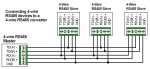
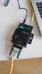
I really need some help. I have a device (inverter) with a Modbus rj45 port and want to connect it to a MGate MB3130 Serial to Ethernet Gateway (to convert from Modbus RTU to Modbus TCP) and test the connection with Modbus Poll. The settings of the gateway should be correct (baud: 9600, parity: None, Databit: 8, Stopbit: 1, Flowcontrol: None). The gateway is set to convert RS-485 4-wire to TCP/IP.
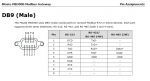
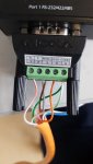
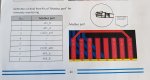
I can't figure out, how to connect the rj45 cable to this gateway. How do I have to connect the cables of the rj45 cable to this db9 adapter? You'll find the necessary pictures attached.

Hope somebody can help me
 

Attachments

Thank you for your response!

I now connected it like the following, see picture
The colors of the cables are:
1: whiteorange (485_B)
2: Orange (485_A)
3: whitegreen (GND)
4: Blue
5: whiteblue
6: Green (GND)
7: whitebrown (485_A)
8: Brown (485_B)

But still, Modbus Poll gives me a timeout error...
I also exchanged the 485_A cables, and also the 485_B cables, but still timeout error.

But funnily, if I connect it as follows:
T+: whitebrown
T-: whiteorange
R+: Orange
R-: Brown
it gives me the "insufficient bytes received" error.

Do you have an idea, where the problem could be?
 

Attachments

There are two options, because it is not clear on the inverter side who is TX and RX:
1)
DB9 RJ45
1 TX(-)A-----orange---------RX(-)A 2
2 TX(+)B--white/orange------RX(+)B 1
3 RX(+)B----brown-----------TX(+)B 8
4 RX(-)A--white/brown-------TX(-)A 7
5 GND---green--green/white--GND 3,6

2)
DB9 RJ45
1 TX(-)A-----orange---------RX(-)A 7
2 TX(+)B--white/orange------RX(+)B 8
3 RX(+)B----brown-----------TX(+)B 1
4 RX(-)A--white/brown-------TX(-)A 2
5 GND---green--green/white--GND 3,6
 
Your inverter is a 2-wire RS-485 device, not a 4-wire. The signals are just duplicated, likely for daisy-chaining purposes.

Therefore you should connect the devices as follows:
MB3130
Inverter
Pin 3 (D+)​
Pin 1 485_B​
Pin 4 (D-)​
Pin 2 485_A​
Pin 5 (GND)​
Pin 3 GND-485​

Note that there is no agreed upon standard for the polarity of "B" and "A" labeling for RS-485. In the above, "B" is assumed to be positive, but you may need to swap the A and B wires, like this:
MB3130
Inverter
Pin 3 (D+)​
Pin 2 485_A​
Pin 4 (D-)​
Pin 1 485_B​
Pin 5 (GND)​
Pin 3 GND-485​

You'll also need to make sure that the MB3130 is configured for 2-wire RS-485.
 
Thanks you two for your help. I tried your suggestions, but it didn't work either. I think the problem is somewhere else...
I also think that the inverter is using RS-485 2-wire, since the manufacturer said that only two wires are needed.
I'm now using another port for the task

Thanks again!
 
You should consider using a computer and a USB to RS-485 adapter to test communications to each piece of equipment separately. You can use software such as ModScan (as the Modbus master) to test communications to the inverter, and ModSim (as the Modbus slave) to test communications to the MB3130.
https://www.win-tech.com/
 
Top