Modbus RTU with a TPW 04 PLC

Hi everyone,

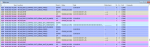
I developped a source code for a Modbus RTU Master. I am able to talk to a large variaty of Modbus RTU PLCs but I can't talk to a TPW 04 PLC. When I send a request to the TPW 04 PLC, I receive the following response 200000 or also 2000000. Can someone explai me why I am unable to connect to this PLC
Thank you
Best regards
 
With the very limited information you provided, it is not possible for anyone to help you. Please reply with the exact data bytes that your Modbus RTU Master is sending and the data bytes that the PLC is responding with.

I also recommend that you try communicating to the PLC using third-party Modbus Master software, such as ModScan, Simply Modbus, or Modbus Poll. Once you have confirmed that you can communicate to the PLC with one of these tools, then try again from your master and compare the data bytes that each are sending.
Thank you for you reply
I already used simply Modbus to communicate with the PLC and there are no problems, the PLC is responding. The problem arises only when I use my source code that I already tested with other PLCs from different vendors.
Here are the message requests sent to the PLC and the corresponding responses

For Coils: We send 2110012525 , we receive 200000.
For discrete inputs: We send 220001185249, we receive 200000.
For Holding register: we send 2367560116112, we receive 204000000.
For Holding Register: We send 2367560116112, we receive 2000000.
For connection tests: We send 28000133248,We receive 20000000.

The requests are in the Decimal format, but the PLC will receive all messages with the Hexadecimal format.

Thank you for your help
 
I'm sorry, but I can't make sense of the data you're showing for the requests and responses. Please show the full requests and responses (including slave address, function code, address, number of points, and CRC fields) and either separate the decimal numbers using a space or write them in hexadecimal so we can distinguish between each individual byte.

Also, how are you determining what data is sent and received? Are you using your Modbus RTU Master software to report this information or are you sniffing the RS-485 bus with a separate tool?
 
FYI, by convention, Hexadecimal is used when documenting the fields in Modbus messages. I don't think I've seen anyone provide decimal numbers before.

Hexadecimal works well because Modbus Holding and Input data registers are 16 bit registers, so each data register is a 4 digit hexadecimal value and the address message field is an 8 bit data word - 2 hex digits.

.
 
I'm sorry, but I can't make sense of the data you're showing for the requests and responses. Please show the full requests and responses (including slave address, function code, address, number of points, and CRC fields) and either separate the decimal numbers using a space or write them in hexadecimal so we can distinguish between each individual byte.

Also, how are you determining what data is sent and received? Are you using your Modbus RTU Master software to report this information or are you sniffing the RS-485 bus with a separate tool?
You are right
These are the requests in the hexadecimal format.

For Coils: We send 2110012525 (02 01 01 00 00 01 fc 05) Output coils address =256 , we receive 200000(02 00 00 00 00 00 ).
For discrete inputs: We send 220001185249 (02 02 00 00 00 01 b9 f9) Input coil address=1 , we receive 200000 (02 00 00 00 00 00 ).
For Holding register: we send 2367560116112 (02 03 43 38 00 01 10 70) Output Register = 17208 , we receive 204000000(02 00 04 00 00 00 00 00 00).
For Holding Register: We send 2367560116112 (02 03 43 38 00 01 10 70) Output Register = 17208, we receive 2000000(02 00 00 00 00 00 00).
For connection tests: We send 28000133248(02 08 00 00 00 01 21 f8),We receive 20000000(02 00 00 00 00 00 00 00).
 
Your requests are valid Modbus requests, which is also confirmed based on the fact that the PLC is responding at all.

However, either the PLC is not correctly sending its responses (which likely isn't the case because Simply Modbus can communicate successfully with the PLC) or your packet receiving source code has a bug such that your CPU is not correctly receiving the bytes. This may be a logical issue or a timing issue.

To confirm, please use a USB to RS-485 converter connected between your Modbus RTU Master and the PLC and capture the bytes sent by each device using a third-party software tool that is capable of displaying received HEX characters (such as this terminal app: https://sites.google.com/site/terminalbpp/).
Thank you jschulze
We are using the Eltima Serial Port Monitor in order to catch the bytes received on the PLC. I think that it has the same function as the software you shared.
 
Dear jschulze,

I am now able to read data from the PLC. The data is read within a loop. From the following table view on which I am monitoring the data read on the serial port of the PLC, I notice that for some requests the data is read (line 4302) and for the other requests, only the slave id is returned (line 4293). Is there any explanation to that. Have I to wait for a moment after sending the request to the PLC before reading the PLC reply.

Thank you very much
 

Attachments

The Modbus specification defines that the end of a Modbus RTU message is marked by a silent interval of at least 3.5 character times. My guess is that your Modbus RTU Master code is not using this 3.5 character time to detect that a full packet was received, but rather simply polling the received bytes some fixed time after sending the request. This is probably why you are seeing only the beginning of packets.

Your code needs to have some sort of packet detection where a 3.5 character timer is started when a character is received. If no more characters are received after the 3.5 character timer expires, you received a full Modbus RTU packet and can now read the packet in its entirety from your higher level code.
 
Can you clarify what you mean by "the response is read"? Does this mean that your program correctly receives the response?

In the table you attached, there does not seem to be a difference between the two transactions shown in lines 4289 - 4293 and lines 4301 - 4305. You stated that line 4302 shows a successfully received response and line 4293 shows only the slave ID. However, I think line 4302 is your request (IRP_MJ_WRITE). The corresponding response is line 4305 (IRP_MJ_READ) and shows just the slave ID of 02, just like line 4293. The table you attached does not seem to ever show a full response in a IRP_MJ_READ line.

It's possible that the reason it's working for some responses is simply due to different response times of the PLC, and only the requests that the PLC responds to quickly are working.
 
Dear jschulze,

I am reading the response of the PLC as a string of hexadecimal characters. Is there any function that i can use to find the corresponding response in the decimal format?

Thank you
 
Hi everyone,

Can someone explain what is the difference between the serial port read function and the readexisting one. When using the readexisting function, question marks appear at the end of the response of the PLC. I read that these question marks appear when the character can not be displayed. Can someone help me converting the output of the readexisting function to the decimal format.

Thank you very much
 
Can you provide more context and details on what it is you're trying to do?

You mention "serial port read function" and "readexisting", but don't tell us what programming language or library these functions come from? For example, are you using C# with .NET? .NET has a SerialPort.ReadExisting method https://docs.microsoft.com/en-us/do...ialport.readexisting?view=dotnet-plat-ext-3.1

I assume that because you're asking how to convert to decimal, you are trying to display the values to a user somehow. Please provide more details on exactly what it is you're trying to do and how you are currently attempting to do it.

It may also be helpful if you include some of your code, since this may be a problem with the code you wrote.
 
Thank you jschulze for your reply
In fact, I am using C# with .NET in fact. I need to convert the response of the PLC to decimal value so that I can display them for the user.
The problem is that for the values returned higher than 127, the readexisting function displays a question mark and I can't display in this case the exact value as the PLC will return Hex caracters and hence decimal values between 0 and 255. Is there any fix for this problem?
For information, I used the read function and it works perfectly but don't understand why the readingexisting function is not performing the same way.
Here is a short sample for the source code. I am reading data received on serial port COM2
SerialPort _serialPort = new SerialPort("COM1", 4800, Parity.Even, 8, StopBits.One);
byte[] vals = {0x01, 0x01, 0x00, 0x00, 0x00, 0x08, 0x3d, 0xff};
_serialPort.Open();
_serialPort.Write(vals,0, vals.Length);
string Data = _serialPort.ReadExisting();
 
Thank you for clarifying. The ReadExisting function is meant to read ASCII characters, as Modbus RTU uses binary characters, you cannot use ReadExisting. The reason for the behavior you're seeing is because the SerialPort class's Encoding property is set to ASCIIEncoding by default, which is a 7-bit encoding, so therefore characters are limited to a value of 127.

Instead, I recommend that you use the ReadByte function and loop until a timeout exception occurs. You will also need to set the SerialPort's ReadTimeout property to 3.5 character times (calculated based on the baud rate, number of data bits, parity bits, and stop bits you're using).

Alternatively, instead of trying to do this yourself from scratch, there are several Modbus .NET libraries available, such as this one:
https://github.com/NModbus4/NModbus4
 
Thank you Jschulze for your reply very usefull
The ReadTimout is needed when I have to read two consecutive responses from the modbus slave. Am I right? I don't need that timeout when to read consecutive bytes?
 
No, it is not possible to receive two consecutive responses from a slave after sending a single request. Modbus uses exactly one response for every request (or no response if the targetted slave does not exist).

You need to set a proper ReadTimeout time for your calls to ReadByte. After you call SerialPort.Write, you should set the ReadTimeout to the maximum amount of time that you want to wait for a response from the slave, then call ReadByte. After receiving the first byte of the packet, the ReadTimeout should be changed to a minimum of 3.5 character times for the subsequent ReadByte calls for that packet. This allows you to detect the end of the packet, since the Modbus specification defines a 3.5 character gap time delimiting each packet.
 
Top