Need advice from a controls expert

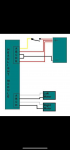
Hey guys, I am doing a 69 Camaro and making my headlite doors open and close with 12vdc wiper motors. Motors are standard 2 wire that use reverse polarity to move in reverse. I integrated a module that provides the reverse polarity based on whether the head lite switch is on or off. I have made it work great as is, however they move very fast and I want to slow down the movement both ways. I purchased 4 speed switches but need to know how I can integrate these into my system. I have provided pics and a rude diagram to explain my intent here. Any help is appreciated. Thx, todd
 

Attachments

@truss1166,

First the three attachments don't seem to show all the same terminals on the headllight module. Is IMG_0705.png a "speed switch"?

Second, we have no idea what kind of "speed switches" purchased.

Third, were there no instructions supplies with the "speed switches"?

Fourth, who manufactured the headlight module and were there no instructions supplied with the module(s)?

My best guess would be that the speed switches have to be between the headlight module(s) and the motor--for the open and close circuits. But, that's a guess because the three attachments are not clear at all--at least to me.

Give us more information and you will probably be pleased with the response(s).
If you're troubleshooting communication issues in an industrial control setup, consider evaluating the PHY layer. I’ve seen great stability using components like the KSZ8081MLXIA, which supports energy-efficient Ethernet and simplifies debugging thanks to its robust design. It might help isolate whether the issue is hardware-related or upstream.
I agree with you, you makes some valid points here. Without clear diagrams or details on the speed switches, it’s tough to give accurate advice. The suggestion to place the switches between the module and motors sounds reasonable, but more info would definitely help. Maybe the OP can share clearer pics or specs so everyone can better assist.
 
Hey guys, let’s see if I can provide more pics/info. Pictures show the module, the speed controller and the 2 wire motor. I will explain each component.
Module is a 5 wire input and 4 wire output. The input/ output provides for 2 motors. Input side with 5 wires is 2 wires for constant power, 2 wires for negative and a switched wire that would normally be switched by a headlite switch. The output wires go to the motors. The module provides both the reverse polarity function and the stop run when motor receives stop resistance.
as it sits right now, I wired the module outputs to the speed controller inputs. Then I wired the output speed controller to the 2 wire motor. My results are that the speed controller works one way when the headlite switch is pressed but will not work when the headlite switch is turned off. So with it wired this way, it is not providing 2 Way operation or providing the reverse polarity to move the motor in the opposite direction. I feel there is a way to put another speed controller in this circuit to get the desired result. And then copy this to make the other motor work. Thx for the time and input/advice on this.
 
Pics are only way I could get them on here. Drawing is of how I have wired it, then the 4 wire speed controller and the module which has the 5 wire input and 4 wire output.
 
@truss1166,

It would really help some of us if you could provide the manufacturer and model number of the speed controller. That way maybe we could download or view the instructions and be more help.

It kind of seems like the speed controller you selected doesn't respond to the reverse polarity when the headlight module changes polarity to close the headlight door. If the input power to the speed module changes polarity (which I think it does from what you wrote) then this particular speed controller doesn't seem to be able to perform the function you want it to. You want it to control speed in two directions--which requires it to accept some kind of input to change the polarity of the output, and simply reversing the polarity of the power input to the switch doesn't seem to be something the speed switch can "interpret" correctly.

Methinks you're going to have source a more sophisticated speed controller. This one seems to want positive power ONLY at the + input terminal, and negative power ONLY at the - input terminal. It is probably some kind of device that can only create a variable output with positive at the + terminal and negative at the - terminal, and is incapable of reversing the output polarity when the input polarity is reversed.

But, Bertus, one of our fine Moderators, has suggested a couple of partner websites where perhaps someone knows of a ready solution or can direct you how to build a simple electronic workaround.

(I wonder if a simple potentiometer (variable resistor) in one of the headlight module output wires--instead of this speed controller you selected or adding another speed controller (increasing the complexity greatly) might be worth a try. Sorry, but I don't know what resistance to tell you to try, but you could get something in the 0-200 ohm or 0-500 ohm range (just make sure it can handle the power (amperes; watts) when the motor is running) and start testing with the potentiometer set to minimum resistance. Then try turning the pot (potentiometer) knob an eighth of a turn and trying the headlight doors in both directions, and then another eighth of a turn of the pot knob in both directions of the headlight doors and seeing what happens. I would suggest some method of being able to stabilize the potentiometer setting you choose (maybe with some silicone caulking somewhere on the knob/shaft?) so that one or both of them don't drift with vibrations and potholes.) I don't think this speed controller you've selected will work the way you want it to without some additional electronics which will overcomplicate the setup--greatly.) Or, choose a DC motor that runs at a slower speed than the windshield wiper motors you are currently using.

I might also suggest looking at some of the Camaro restoration forums on the World Wide Web to see what others have done or are doing--if you haven't already.

Please let us know how you fare in resolving this problem.

(P.S. I had a '69 RS (I think it was an RS--it had the headlight doors, anyway) in the late 70's that I was building a big-block engine for to bracket race (drag racing). I changed career paths and ran out of money and ended up selling everything to someone who finished the project--then crashed the car in the second race it ran. Only the owner's wallet was injured.... I wish I had that car now. I saw another '69 Camaro once that the owner had converted the front end to be able to tilt up (forward--it required two people to do it) to get easy access to the engine, also a big block with beautiful Hooker Headers and lots of chrome--including the radiator. (It didn't have inner fender wells so I don't think he intentionally drove it in any rainstorms.) It was so unique and beautiful. Now I have the time and the money, but there aren't '69 Camaros where I live now.)
 
Hello thank you for the detailed reply. I like your suggestion about using a pot. I also purchased four of these little speed controllers, thinking that I might hook up 2 per each headlite door to control each positive leg of each door motor. My thought was somehow to wire them as to maybe share the negative pole on each direction, if that makes any sense. I am not sure how to do that but maybe??? Thoughts?? Also 69 Camaros are really kool for sure. For some reason my preference is for only the RS package with the hideaway lites. Slowing them down though would be nice. I made it work one way, got to be a way to have it both ways. lol…
 
@truss1166,

I don't see four wires from the headlight controller or speed controller to the wiper motors being used to operate the headlight doors. I believe you said the polarity was reversed on the two wires by/from the headlight controller to the wiper motors. If there was a "open" positive and negative AND a "close" positive and negative your suggestion would work. I'm not even sure that two pots per wiper motor would work--it might, but I'm not sure. I don't know if two pots per wiper motor are really necessary because all you are trying to do is insert some resistance into the circuit to limit the voltage going to the wiper motor--and you can probably do that with a single pot in one of the wiper motor leads. Maybe. Probably. But, honestly, I'm just SWAGging it here (Scientific Wild-Arsed Guessing) on this issue.
 
Somebody suggested to me today to put the speed controller on the line side of the speed controller instead. It can operate between 6 and 24 vdc. Might be an idea.
 
I don’t know what I was thinking when I put that comment. I still haven’t figured this out. I don’t know how to integrate the reverse polarity factor into this to make it work.
 
Hi,
The speed controller looks like it was some thing purchased off Amazon and controls the speed of a DC motor by changing the duty cycle of the voltage applied to the motor. There is no reverse connection.
What I would suggest is wiring a couple of relays between the speed controller and the motor that will revers the polarity for directional control. You could use 2 relays with 2 from A contacts each or 1 4 pole relay with form C contacts.
If you chose the second method energize the relay when the light switch is on and the motors can use the N.O. contact to Open. When the switch turns off the N.C contacts can move the motor in the opposite direction.
I am assuming that the controller shown in one of your pictures shuts off power to the motors when they are fully open / closed. If not you will need overtravel switches. If that is the case it would be be easier to implement with 2 relays. The over travel switch could turn off the appropriate relay.
 
Top