Older relay logic based booster pump system which I would like to upgrade to a basic plc based system

I'm currently trying to develop some knowledge about relay logic control systems specifically related to domestic water booster pumps.
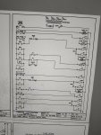
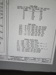
One of the buildings at my work site has an older Canariis corp. packaged booster system that seems outdated. It has a jockey pump #1 (less hp rating) and then 2 equal higher hp rated booster pumps labeled #2 and #3. I'd like to graduate from diagnosing (with help) the current problem with this system as well as learn how to upgrade components in the control panel to a logic based system by switching out various sensors tied to a basic programable logic board. This is a big undertaking for me but I am the type to see it through and it also being the best way I tend to learn (hands on). If anyone has experience dealing with older relay logic type controls vintage 2005ish(?) I'd be very grateful for suggestions that lead me to success. I have the Ladder diagrams and other data which I can attach to this thread if so.
thanks
Joe
 
The factory where I first started working was all controlled by relay logic. To change to PLC logic all the switches etc would be wired to inputs and all the motors etc would be wired to outputs via contactors. Post the electrical schematic so we can see how complex the circuit is.
 
The factory where I first started working was all controlled by relay logic. To change to PLC logic all the switches etc would be wired to inputs and all the motors etc would be wired to outputs via contactors. Post the electrical schematic so we can see how complex the circuit is.
Here are copies of the ladder diagram for the triplex booster pump relay based contrrol panel
 

Attachments

The problem currently is that the jockey pump #1 runs continuously... as though pressure is never "made" which I believe is why it eventually blow a fuse. I replaced the fuse and it runs ok but I'm sure will blow another fuse soon. I suspect the issue is a pressure switch not recognizing when 80psi is "made" leading pump one to run continuously. The attched ladder diagram looks pretty complex to this untrained eye for sure.
 
The ladder diagram is not too complex, I have provided some information below, if you get stuck I can provide more. If you want to develop your knowledge you will need to gain an understanding of a relay holding circuit, delay on timers and minimum run timers. One of the sheets you posted lists the functions of the timers, TO - after the timer is powered for a set time the contacts switch, TI - when the timer is powered the contacts switch then after a set time switch back, the descriptions of the timers should help you under stand the circuit and I have added descriptions for the relays below:
R3 High System Pressure Tripped Relay
R4 Alarm Silence Relay
R5 Low System Pressure Relay
R7 Low System Pressure Tripped Relay
R8 Run Pump 1 Relay
R11 Run Pump 1 and Pump 2 or 3 Relay, (2 and 3 alternate at each start)
R14 Run Pump 2 and 3 Relay
ALT Alternating Relay
If the problem was the Call pressure switch then I would expect another pump to run continuously once the R9TO timer expires. If it is just pump 1 then it could be R15TI sticking in.
What sort of timers are being used? are they electronic timers or pneumatic timers?
Thank you for all the above info. I will pour over it and try to connect the dots/sequences. The timers are electronic and build into the relay icecubes. They are about twice the height of the regular relays and have what look like adjustable time dials on them. After reading your thoughts I think I get how I should look towards the R15T1 relay being faulty as it is just pump one with no other pumps turning on after any amount of time.

One question I have is the BARKSDALE "CALL PS" pressure switch. Am I thinking this correct that with it wired NC it means that it will cause pumps to run until pressure is made which opens the circuit? and when pressure falls enough it closes again turning on the pump? Could the issue be that the pressure switch is faulty and never opening? but then at some point after the relay timer times out a 2nd or 3rd pump should turn on if that were the case (?)
Thanks for your guidance!
 
The ladder diagram is not too complex, I have provided some information below, if you get stuck I can provide more. If you want to develop your knowledge you will need to gain an understanding of a relay holding circuit, delay on timers and minimum run timers. One of the sheets you posted lists the functions of the timers, TO - after the timer is powered for a set time the contacts switch, TI - when the timer is powered the contacts switch then after a set time switch back, the descriptions of the timers should help you under stand the circuit and I have added descriptions for the relays below:
R3 High System Pressure Tripped Relay
R4 Alarm Silence Relay
R5 Low System Pressure Relay
R7 Low System Pressure Tripped Relay
R8 Run Pump 1 Relay
R11 Run Pump 1 and Pump 2 or 3 Relay, (2 and 3 alternate at each start)
R14 Run Pump 2 and 3 Relay
ALT Alternating Relay
If the problem was the Call pressure switch then I would expect another pump to run continuously once the R9TO timer expires. If it is just pump 1 then it could be R15TI sticking in.
What sort of timers are being used? are they electronic timers or pneumatic timers?
Sorry, after re-reading your post I see you answered my question, "If the problem was the Call pressure switch then I would expect another pump to run continuously once the R9TO timer expires. If it is just pump 1 then it could be R15TI sticking in"

Am I understanding the action of the "Call pressure switch" though? IE. always on unless pressure is satisfied and then opens, shutting off the pumps (?)
With the other Barksdale pressure switches being used as safety devices for either: pressure too high, suction too low, system pressure too low (?)
 
Am I understanding the action of the "Call pressure switch" though? IE. always on unless pressure is satisfied and then opens, shutting off the pumps (?)
Yes
With the other Barksdale pressure switches being used as safety devices for either: pressure too high, suction too low, system pressure too low (?)
High System Pressure Tripped and Low Suction Pressure tripped will stop the system and trigger the alarm. The Low System Pressure Tripped will start the pumps, the same as the Call pressure switch. I presume it should never get this low under normal operating conditions.

When pump 1 is staying on has the required pressure been reached? If the pressure is still too low, the fault could be the other pumps not starting due to R9TO, R11 or ALT.

You should check the settings of all the pressure switches and timers when you are trying to work out the circuit.
 
Yes

High System Pressure Tripped and Low Suction Pressure tripped will stop the system and trigger the alarm. The Low System Pressure Tripped will start the pumps, the same as the Call pressure switch. I presume it should never get this low under normal operating conditions.

When pump 1 is staying on has the required pressure been reached? If the pressure is still too low, the fault could be the other pumps not starting due to R9TO, R11 or ALT.

You should check the settings of all the pressure switches and timers when you are trying to work out the circuit.
Thanks for sharing your thoughts. While pump #1 is running the analog gauge is reading apprx 85 psi which should "make" the pump and shut it down (pressure switch setting is 80 psi) but it keeps running. As a side note I've been keeping pump #1 shut down via HOA in off. This leads pump 2 and 3 to alternate and they too will never shut down even though gauges are reading 85psi.
The continuous alternating between 2 and 3 seems normal and in a timed manor which I suspect is better than leaving #2 or both #2 and #3 in hand while trying to diagnose the issues. Should I adjust "call p.s." lower to see if the system pressure can be made? to rule out weak pumps/motor?
Did I read you correctly that "low system ps" starts the pumps and "call ps" also starts the pumps? It's still vague to me about what the normal cycle should be with regard to low system ps and the call ps when everything is operating normally.
Thank you for your patients!
 
As a second pump is being called, it seems like the pressure switch is not switching off either due to pressure switch fault or not enough pressure from pumps.
Are there any indicators on the relays to tell you they are energised? LED or mechanical indicator. You could video these while problem is occurring then diagnose more later.
You could just run the system in manual by switching various pumps to manual/off and see when R8 switches on/off.
There will be some hysteresis in the pressure switch, so the "call pressure low" will be lower than the "call pressure ok" by a small amount.
Normal cycle should be:
1. Call PS low or Low System PS and Tripped: P1 On, for minimum on time of T15 (1 pump on)
2. P1 On and T9 done: P2 or P3 on, for minimum on time of T10 (2 pumps on)
3. P1 On, T9 done and T12 done: Remaining pump on, for minimum on time of T13 (3 pumps on)
Stop: Call PS ok and Low System PS ok or not Tripped - all pumps off (after minimum on times above if not already expired)
 
So to update the status of this setup is pumps 2 and 3 are alternating with the jockey pump turned off. I thought a good approach is to upgrade this system one step at a time by eliminating the relay logics and installing a PLC programmed to simply alternate pump on a timer basis...every 12 hours perhaps, with the ability to shut off when/if system pressure is made and or suction pressure gets too low. Inputs would be 2 analog pressure sensors(?) the rest can be transferred from the existing control panel ie: HOA switches, indicator lights etc. I've been reading a lot of PLC basics and have been practicing with Rockwell automation simulator software.. which is great building out Ladder Logics but I have not grasped the electrical mind set to connect the various I/O's in the order that they need to go. It will take sometime. In the mean time would you happen to have a cookie cutter ladder logic layout of a 2 pump domestic booster system with pressure switches, timer sequences etc ? That I can copy wiht the simulator software and thus boost me along in the learning curve?
 
Good to see you are making progress. I am not sure why you have the jockey pump off, I thought it would be useful to make up pressure with low or no flow, a larger pump would not be required to start.
One step at a time is good but at some stage there will need to be a big step to replace the core relay logic. Software simulator is a good way to prove your logic beforehand.
Analog sensors are a good idea, you just need to consider worst case if something goes wrong with a sensor and pumps stay on continuously. Will this damage something? Should you have a backup switch or sensor to detect something has gone wrong?
I don’t have any cookie cutter logic for your application. The best solution depends on your approach to programming. The electrical schematic can be the basis for your ladder logic, just broken up into rungs as required. Alternatively, you could write a sequence in ladder logic, with different steps controlling the pumps.
 
Thanks for your reply,
Jockey pump off because it may blow another fuse also the building is only 2 stories high and I work in buildings where they are using an older switching relay (on 24 hour timer) to alternate 2 pumps one at a time to maintain pressure 10 floors high... not the best set up for sure.
I'm thinking about building a flip flop based alternating 2 pump system but I'm thinking flip flop basis because it's the first one I've learn about in plc programing. Any thoughts on what is the industry standard for alternating pumps, if there is a common standard programmers use that is better than flip flip design?
thanks
Joe
 
If I was alternating pumps with a PLC program, I would have lead/lag code. Before the first pump is started it selects the pump with the lowest run hours as the lead.
 
Top