Temp errors!

Good day,

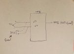
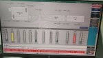
We are currently having issue with our MS5002B gas turbine exactelly in centrifugal compressor thermocouples. the GT is stopped and the Lub oil circulation is in service.
As mentioned in pics, some of thermocouples r good (TE 623, 626, 650,653) & the rest r out of range!!
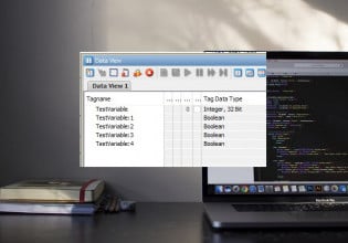
We checked them in site and in the pannal of MARK VIe ( the entre of I/O pack), we found them approximately in the same value (22C°), but in HMI r in wrong value as they mentioned in pic.
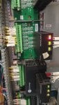
We thought that the problem lies in the PTCCH1B pack or STCC termibal board, we changed both of them & Pb remains the same!

Please kindly assist with any info on what to do next & Thank you for your help and your patience.
 

Attachments

mahad83,

I'm impressed you took a photo of the Diagnostic Alarms for the PTCC...! Have you tried doing any of the recommended troubleshooting for the alarms? If so, what were the results? (Or, did you just go straight to replacing the I/O Pack and terminal board(s))?

What happens when you unplug the terminal board section to which the the T/C extension wires are connected to? It WILL NOT hurt anything to just pull the removable section away from the stationary section of the terminal board with the I/O Pack powered up? And, then try resetting the Diagnostic Alarms?

Without more information it would seem there is some electrical "noise" interference coming in on one of the T/Cs connected to the problem terminal board (as suggested in the Diag. Alarm texts). It may be some kind of short or ground (though the Mark VIe can work with grounded or ungrounded T/Cs--so a ground shouldn't be the problem, but ... ). But it would seem to me that if you disconnect the T/Cs from the terminal boards, although you will get new, different Diag. Alarms (indicating the signals have failed/are open circuited), if these unusual Diag. Alarms go away (the ones about reference voltage and CJ (cold junction)) then it's probably a wiring issue or some kind of induced electrical noise on the T/C extension wiring.

When something like this happens, the first thing to be considered should be: What has changed in the area where the problem seems to be located? (In this case, the centrifugal compressor.) Did someone disconnect T/Cs or T/C extension wires and not reconnected them properly? Has someone added a new cable to a cable tray or cable put that violates signal level separation for low voltage signals (which is what T/C signals are--very low voltage)? And, then try to determine what was/wasn't done that lead to the problem. If the unit has been working well for a while since commissioning, and this just started--it's very likely something that was/wasn't done in the area or the cable tray/pit that is causing electrical problems leading to the Diag. Alarms shown in the photo.

Please write back to let us know what you find and how you resolve the problem. It would also be VERY helpful if there was some work done that led to the start of the problem if you told us--a LOT of people read these posts and learn from them....

Hope this helps!
 
Thnk's for ur answer,
I forgot to explain something else to you to clarify the problem more.
At the entrance of terminal board and for each T/C, we take a cable to connect it in ABB DCS ( just for display) and that r good! they give the same value in area!
 

Attachments

mahad83,

Take a picture of the T/C values from the Thermocouples tab of the same PTCC I/O pack you took the photo of the Diag Alarms from and post it to this thread.

How long have you been jumpering the signals to the DCS???

What happens to the Diagnostic Alarms when you disconnect the T/Cs from the STCC????!!!!?!??!!!
 
Any chance your issue with bad temperture readings coincided with your action "for each T/C, we take a cable to connect it in ABB DCS ( just for display) and that r good!" (post #3)?

Paralleling a thermocouple signal to different receivers (analog inputs on different devices) can work. The heat treat industry did it for decades. But not always, there's no guarantee; it can go wrong.

Paralleling a thermocouple output works if

1) there is no common mode voltage ground loop developed between all devices. A low level ground loop will 'offset' the value (positive or negative, depending on polarity); a mid level ground loop can saturate the analog input circuit driving the reported temperature off scale, up or down, or a really bad ground loop can burn out the analog input circuits.

2) one analog input's thermocouple break circuit does not interfere with the signal acquisition on the other analog input. Some analog inputs' thermocouple break circuits would drive a current through the thermocouple which could offset or drive the other analog input signal offscale.

I don't know of a means of determining in advance whether paralleling a thermocouple to two devices will work or not - it's always been an empirical experiment to determine that.
 
mahad83,

I was SO happy to see a photo of Diagnostic Alarms I completely forgot to ask: When did this issue with the T/Cs start?

This is a very important question, and the forgotten tidbit about jumpering the T/C signals to the DCS just shouts, What else don't we know?

Why aren't you using T/C isolators to split the T/C signals to send the same signal to the DCS?

Why aren't you using MODBUS to send the T/C signals to the DCS?

Why are you using mA outputs of the Mark VIe to send the T/C information to the DCS?

To David_2's excellent point--it's been demonstrated MANY times that T/C signals in a Mark* control system can be jumpered to multiple points (NOT always, but for these particular modules it has worked many times). BUT, trying to jumper the same signals as you are doing to another control system is usually a trial-and-error affair--meaning it's "plug-and-pray" (not plug-and-play).

1) Tell us when this problem started.

2) Show us a photograph of the Thermocouples tab of the PTCC I/O Pack with the T/Cs connected to the STCC AND the T/Cs jumpered to the DCS.

3) Show us a photograph of the Thermocouples tab of the PTCC I/O Pack with ONLY the bearing metal T/Cs connected to the STCC (in other words, disconnect BOTH of the T/C extension wires jumpering from the STCC terminal board to the DCS T/C input terminal board).

4) Show us a photograph of the Thermocouples tab of the PTCC I/O Pack with the removable portion of the STCC terminal board disconnected from the stationary portion of the STCC.

THEN we can have a meaningful discussion--WHEN you provide the above information.

*What I'm asking for is to show us the tab which lists the T/C input values of the PTCC I/O Pack--I think that's the Thermocouples tab; it may be another tab. But there IS a tab which lists all of the T/C values of the input channels of the I/O Pack--that's what we're asking for.
 
We have three unites wth the same installation. U1, U2 &U3.
This problem in only in U3! the other both unites are good eventhough the same connection of T/Cs wth DCS about a year ago from the revemping the system of control MARK II to MARK VIe.

The machine U3 was working very normally, only when we wanted to turn it on, this problem appeared.
mahad83,

I'm impressed you took a photo of the Diagnostic Alarms for the PTCC...! Have you tried doing any of the recommended troubleshooting for the alarms? If so, what were the results? (Or, did you just go straight to replacing the I/O Pack and terminal board(s))?

What happens when you unplug the terminal board section to which the the T/C extension wires are connected to? It WILL NOT hurt anything to just pull the removable section away from the stationary section of the terminal board with the I/O Pack powered up? And, then try resetting the Diagnostic Alarms?

Without more information it would seem there is some electrical "noise" interference coming in on one of the T/Cs connected to the problem terminal board (as suggested in the Diag. Alarm texts). It may be some kind of short or ground (though the Mark VIe can work with grounded or ungrounded T/Cs--so a ground shouldn't be the problem, but ... ). But it would seem to me that if you disconnect the T/Cs from the terminal boards, although you will get new, different Diag. Alarms (indicating the signals have failed/are open circuited), if these unusual Diag. Alarms go away (the ones about reference voltage and CJ (cold junction)) then it's probably a wiring issue or some kind of induced electrical noise on the T/C extension wiring.

When something like this happens, the first thing to be considered should be: What has changed in the area where the problem seems to be located? (In this case, the centrifugal compressor.) Did someone disconnect T/Cs or T/C extension wires and not reconnected them properly? Has someone added a new cable to a cable tray or cable put that violates signal level separation for low voltage signals (which is what T/C signals are--very low voltage)? And, then try to determine what was/wasn't done that lead to the problem. If the unit has been working well for a while since commissioning, and this just started--it's very likely something that was/wasn't done in the area or the cable tray/pit that is causing electrical problems leading to the Diag. Alarms shown in the photo.

Please write back to let us know what you find and how you resolve the problem. It would also be VERY helpful if there was some work done that led to the start of the problem if you told us--a LOT of people read these posts and learn from them....

Hope this helps!

We have three unites wth the same installation. U1, U2 &U3.
This problem in only in U3! the other both unites are good eventhough the same connection of T/Cs wth DCS about a year ago from the revemping the system of control MARK II to MARK VIe.

The machine U3 was working very normally, only when we wanted to turn it on, this problem appeared.
 
mahad83,

This keeps pointing to some wiring problem. If you've replaced the PTCC AND the STCC and the problem persists, then it's likely NOT inside the Mark VIe panel. (And, it's possible that if it's a wiring problem outside the Mark VIe panel that the PTCC and/or the STCC is being damaged by the problem! So, replacing the pack/card is simply wasting money (and time).)

AGAIN, if you would try what was suggested--ONLY as a TEST (it's not being suggested as a permanent fix)--you might find the problem(s).

At this point, I'm done. Can't do anything without actionable data--and dribs and drabs of information.

Best of luck.

Blessed day.
 
Many newer versions of ToolboxST have the feature that pops up 'Help' information for Diagnostic Alarms when they are double-clicked on.

The SAME information for any Diagnostic Alarm is also found--usually--in GEH-6721, Vol. II, 'The Mark VIe System Guide.' One scrolls to the relevant section (in this case, it would be for the PTCC I/O Pack), and then find the Diagnostic Alarm sub-section, find the Alarm ID number(s), and there will some brief explanation of the alarm text message(s), and usually, a suggested way to resolve the alarm.

There are LITERALLY thousands of possible Diagnostic Alarms--THOUSANDS! So, don't ever expect to find comprehensive help for Diagnostic Alarm messages. The text of messages of Alarm IDs 24 and 20 in one of the photos above indicates that there is no IONET communication between <R> and the PTCC I/O Pack in location 1A2B. This could suggest a 28 VDC power supply issue, or an IONET cable issue, or a failed I/O pack. There were some IONET network switches which had known issues with some of the RJ-45 receptacles, and it is also possible that one or more of the "wires" used to connected the switch to the Ethernet cable end has been damaged and is bent or shorted.

World Wide Web forums like this one can offer some troubleshooting help and tips and in some cases some tricks or solutions. BUT, there is no substitute for having knowledgeable people come to site to help resolve issues. In this case, it seems very warranted (to have a knowledgeable person travel to site to help with the troubleshooting and resolution). It's often said, "We tried THAT--and it wasn't the problem!" Well, sometimes the test method isn't executed properly or completely, and when it's tried again with a more logical and thorough approach, sometimes magic happens. It's not possible to stress enough--when troubleshooting an issue like this, it's best to write down everything that's attempted, HOW it was attempted, and PRECISELY what the results were (screen captures and photos are very helpful in this regard). Many times a knowledgeable person goes to site and is RIDICULED for doing the SAME THING site personnel tried, but with VERY different results. Site people can be easily offended and site management DOES NOT like to pay someone to do something their personnel has already tried--but with unsuccessful results. So, if there's a desire to limit the knowledgeable person's time when brought to site, it's best to DOCUMENT every troubleshooting step taken, HOW it was performed, and WHAT the results were.

It's pretty clear that the basics of Mark VIe operation and configuration are not understood at this site. So, again, it's strongly recommended to have someone knowledgeable come to site and help troubleshoot and resolve the issue. I suggest that before doing so that a NEW, UN-TRIED PTCC I/O Pack and NEW, UN-TRIED STCC terminal board are on site in case the ones which were previously used and replaced are damaged (because of lingering field issues (wiring; terminations; etc.)).

If a Diagnostic Alarm says there's no communication between a control processor (<R> in this case) and an I/O Pack--they communicate via the IONET--using Ethernet cables and Ethernet switches, there's no communication. Now the problem may be that the power supply to the I/O Pack is "bad" (the power supply cable was not plugged in properly), or the distribution board that the power supply cable gets its power from is bad. It could be the IONET Ethernet cable isn't properly inserted into the RJ-45 connector on the I/O Pack, or the wires in the RJ-45 connector used to connect the cable to the pack are bent or damaged. Or, the I/O Pack has simply failed. It could be that the I/O Pack wasn't properly inserted into the receptacle on the STCC. But, when the Diagnostic Alarm says no communications--it means the communication path/network isn't allowing communications. There are LOTS of diagrams and pictures in GEH-6721 that explain the IONET and how it works and how it's interconnected to different packs and switches and control processors.

Blessed day.
 
Radio silence. Must have been a wiring problem. :cool:
I'm so sorry for answer. I really was basy. :)
Here, as you told me, we found the problem on two faulty thermocouples on site which prevent the others. And the indication on DCS was wrong.

Thnsk you so much. You do a great job in this group.(y)
 
by the way Mr: CSA,
I have another problem with the sealing oil level indicator on the centrifugal compressor. The transmitter displays 60% and the level glace LG of the tank indicates 60%, but on the HMI of the MARK VIe indicates 16% (low level)!!
 
Top