Facebook
 Google
 GitHub
 Linkedin
I am Henry from Ghana.
A student learning how to use the Logo8 PLC and WinCC.
I have installed LOGO Comfort V8.3 and WinCC V.8.0 and my PLC hardware is 6ED1052-1MD08-0BA1
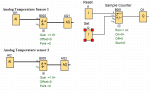
I am developing a monitoring system to monitor two different temperature sources and also a sample counter unit.
I Load the program and perform a successful online test.
The logosoft diagram for the design is attached.
I then select Modbus connection for LOGO and WinCC connectivity in the Logosoft.
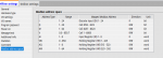
I then launch my WinCC to input tags and addresses and for the CPU; I select Compact, quantum, and momentum.
The Modbus TCP/IP shows connected with the check sign when I activate the WinCC in run time.
In the logosoft Modbus address space I then select the mapped Modbus address
I used 1 of 8 for analog input thus input register and for holding register for analog output I used 513 out of 520.
For the counter, I am not certain what address to use for the set and reset and the counter registers itself in the wincc tag management.
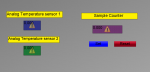
When I activated the wincc run mode I got the output attached.
1 My question is What data type and address type should I select in the WINCC tag management for the sensors to read the temperatures? and display them in the IO FIELDS
2. Also what data type and address should be selected in the WinCC tag management for the counter to display in the IO FIELD?.
3. Generally is there something I have not done right or connected correctly,
Please advise.
A student learning how to use the Logo8 PLC and WinCC.
I have installed LOGO Comfort V8.3 and WinCC V.8.0 and my PLC hardware is 6ED1052-1MD08-0BA1
I am developing a monitoring system to monitor two different temperature sources and also a sample counter unit.
I Load the program and perform a successful online test.
The logosoft diagram for the design is attached.
I then select Modbus connection for LOGO and WinCC connectivity in the Logosoft.
I then launch my WinCC to input tags and addresses and for the CPU; I select Compact, quantum, and momentum.
The Modbus TCP/IP shows connected with the check sign when I activate the WinCC in run time.
In the logosoft Modbus address space I then select the mapped Modbus address
I used 1 of 8 for analog input thus input register and for holding register for analog output I used 513 out of 520.
For the counter, I am not certain what address to use for the set and reset and the counter registers itself in the wincc tag management.
When I activated the wincc run mode I got the output attached.
1 My question is What data type and address type should I select in the WINCC tag management for the sensors to read the temperatures? and display them in the IO FIELDS
2. Also what data type and address should be selected in the WinCC tag management for the counter to display in the IO FIELD?.
3. Generally is there something I have not done right or connected correctly,
Please advise.
Attachments
-
 16.4 KB Views: 1
 -
 60.9 KB Views: 4
 -
 26.5 KB Views: 3