Facebook
 Google
 GitHub
 Linkedin
Applications of Geometric Dimensioning & Tolerancing (GD&T) and Machine Vision in Manufacturing
A look at how cameras are used to detect GD&T based on the resolution of the camera, and how to achieve higher tolerances by using a differential waveform.
Geometric dimensioning and tolerancing (GD&T) has been a staple of design and manufacturing. Measuring devices such as calipers and micrometers can be found on machinists, CNC operators, and engineer’s desks around the world. While CAD software is making design easier, there are many processes that happen from the designer's computer to holding the finished part.

The Basics of Geometric Dimensioning and Tolerancing. Image used courtesy of Formlabs Inc.
Automation and IIoT are driving modern manufacturing to maintain or improve autonomous digital threads of documentation and quality validation. One of the main drivers of these technologies is the demand for speed. Production is becoming faster, more customized, increasing the need for greater fidelity in testing and validating GD&T. Six Sigma can help statistically improve processes to reduce GD&T rejected parts, but even if you have three sigma, manufacturers still have to find about three out of a thousand parts.
Automating Geometric Dimensioning and Tolerancing
Digital transformations are using technology to check each part’s GD&T and some manufacturing lines are able to do it for each step of the process. This level of fidelity provides several things including:
- Assurance that each part is within design GD&T and has documentation
- Reduce wasted time and energy on failed parts that would have continued down the manufacturing line
- Show treads on GD&T variance that could indicate maintenance concerns for predictive maintenance
Replacing the Micrometer
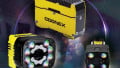
Visual sensors and software are providing higher fidelity and automation in quality testing. Digital cameras have become robust, advanced, and cost-effective to perform accurate GD&T analysis at great speeds. To understand how a camera is able to replace traditional measuring tools, first look at the field of view (FoV) and resolution.

A pixel resolution reference value. Chart used courtesy of Keyence.
The resolution is associated with how many pixels a camera has. With a 2 megapixel camera, there are 1,200 by 1,600 pixels. The field of view is, in short, the amount the camera can see, which will change with the distance between the camera and the object. From this and some math, the pixel resolution of the camera can be determined.
Example
Use the Y axis, or the axis with the least amount of pixels (P) to find the pixel resolution (A). For a two-megapixel camera, it is 1,200. For this example, the FoV is 100mm or just under four inches.
FoV / P = A
For this example, without additional tools or software, a two-megapixel camera has a pixel resolution about 3.3 thousandths of an inch. According to Keyence, “In dimension inspection, the tolerance used as a threshold for differentiating good and defective workpieces is usually calculated in units of ±5 pixels. This is based on the assumption that the number of pixels that ensures stable tolerance judgment is about 10 times the repeatability. Since the repeatability of typical vision systems is about 0.1 pixel under ideal conditions, the practical repeatability is considered to be 0.5 pixel with some margin included. Multiplying this number by 10 yields ±5 pixels, and this value can be regarded as the minimum unit for tolerance setting.”
With this in mind, the actual dimensioning tolerance of a two-megapixel camera would be 0.0033” x 5 = 0.016 or 1.6 hundredths of an inch.
Unfortunately, this dimensional accuracy will not work for many applications. It is possible to improve dimensioning tolerance with higher resolution cameras, or by changing the FoV. However, the software has evolved to make accurate measurements within one pixel.
Focusing on Math
Manual measurements can take advantage of human eyesight and physical contact with datums and edges to determine distances. Defining edges on an image is not as easy. Zooming in on an image often doesn’t result in a straight line of pixels representing an edge, but rather a wavering blend of white, grey, and black pixels.
As previously shown, trying to determine where the edge is is not accurate enough to simply assume that an edge is within a few pixel areas. However, using data from multiple pixels can be used to help find edges of objects. Digital images register a number associated with the amount or intensity of light in each pixel.
Using these numbers, the software can generate a differential waveform to find the peak or highest point of the wave which indicates the edge of an object. Some software is able to provide dimensioning data to 0.001 of a pixel. Subpixel processing is able to perform GD&T testing fast and autonomously to increase fidelity, documentation, and help maintain a full digital thread.
As production speed increases, finding solutions to maintain or increase GD&T inspections will become imperative. Advancing vision sensors and software will continue to drive smart camera technology to ensure quality control can improve without slowing production.