Facebook
 Google
 GitHub
 Linkedin
A New Way to Pneumatic: Industrial Piezo Electric Valves
The term "piezo" refers to a relationship between mechanical deformation and voltage–useful for some sensor processes. Recently, the concept has been employed to upgrade pneumatic valves.
Fluid is one of the oldest forms of power transmission, with roots spanning long before electrical controls entered the scene. Harnessing the power of air, water, and steam has become easier and more efficient over the years into the modern era.
Historically, the most effective method of controlling fluids was by use of either electrical valves or spring-loaded mechanical valves, depending on the intended outcome. Some valves limit pressure, some limit flow rate, while others simply provide a direction of flow. Most of the electrical versions use solenoids (linear motion from coils) or motor-driven actuation to achieve precise control, and that’s still a great choice for many applications.
However, a new player has entered the game, and while the driving technology isn’t new, its application to pneumatic controls is still quite unfamiliar to most engineers. This concept is called the piezoelectric effect.
I was fortunate enough to learn about this technology in a recent interview with Daniella Gonzales, the Valves Product Manager from Festo, who also deserves credit for providing visuals and diagrams.
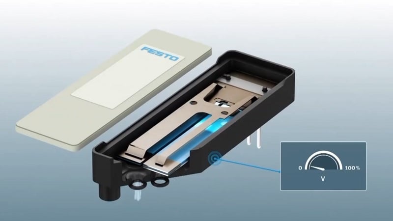
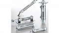
Figure 1. Piezo valves work with high voltage, but they provide the precision necessary for sensitive applications. Image used courtesy of Festo
What Does Piezo Mean in Electronics?
Although material science is complex, the effect is fairly simple. When certain materials are subjected to stress (pushed, bent, hit with a hammer, etc.), they generate a voltage. Other real-world quantities generate a voltage when they are subjected to change:
- Seebeck effect: temperature
- Photoelectric effect: light
- Electrostatics: frictional motion
Most of these voltages are quite small, and the piezoelectric effect is no different. The generated voltage will be small unless the deformation is quite large.
Not all materials exhibit this property; you can’t simply bend a paperclip and expect to generate electricity. It’s most commonly found in some ceramics, polymers, and even a few organic materials.
Converse Effect: Causing Deformation
This effect is a two-way street, and that is a critical factor in understanding its use in pneumatic valves.
We have stated (and it has been proved many times) that applying deforming stress generates a voltage. Conversely, applying a voltage to certain materials causes a bending or deformation of the material. In other words, we can cause movement by applying electricity. One significant challenge is that it requires a lot of voltage to deform the material, even a slight amount.
In the past, the only go-to mechanism for generating motion was electromagnetism, which included motors and solenoids. Piezoelectric motion is a good alternative, but it’s not always the best solution, so it’s not likely to be a drop-in replacement for all motion any time soon!
Applying Piezo Materials to Pneumatics
Inside any valve (directional, flow control, pressure regulation, whatever), pieces must physically move. The inside passages open and close to extremes in a DCV, while they open with some level of precision inside process control valves. The piezo device allows variable, precise control, so it’s a great fit for pressure regulation and flow control, but it can also be leveraged for directional valves.
Inside the valve, an inlet port is blocked by a strip of piezo material. When voltage is applied, the material bends, opening the internal passage and allowing air to flow to the outlet.
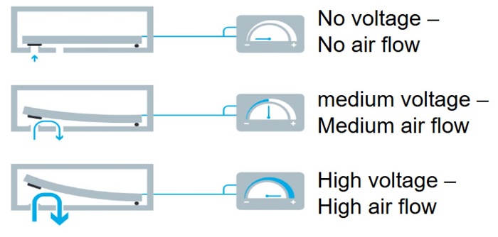
Figure 2. Voltage provides the bending force, which is why they are called "benders." Image used courtesy of Festo
High Voltage
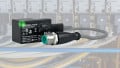
We mentioned one challenge that stands in the way: it requires high voltage to operate. This may be 10x or higher than the typical 24-volt system for traditional pneumatics. Piezo valves are supplied by voltage modules that convert a lower voltage at a higher current to a high voltage, but at an extremely low current, thus still conserving power over solenoid valves.
These modules often convert an analog 0-10 V or 4-20 mA into the high voltage required to open the valves proportionally. When power is removed, the bender remains in place until another voltage closes the valve. Therefore, these valves usually have three input wires: Gnd, Open, and Close. Since they stay in place, the valves only require a low-current pulse to activate, and then power is conserved after that. It’s a major energy reduction compared to solenoids.
Pressure Regulation
The concept of a pressure regulator is to allow a certain amount of pressure into a system, then close when the pressure reaches a pre-defined limit. This is normally done with a spring-loaded valve that provides its own feedback, closing itself the moment the pressure inside the system reaches the limit.
When a piezo valve with one internal bender is paired with a pressure sensor, this process becomes completely digital. The major advantage is that the pressure can be dynamically adjusted to accommodate different loads. When a computer controls the regulators, they can be placed at each point of application and adjusted as the situation changes. That could never be attempted with spring-loaded mechanical valve adjustments.
Flow Control
Similarly to pressure regulation, flow control traditionally uses a variable needle valve that remains in a constant position to allow air to flow with more resistance than an open pipe. These valves are commonly attached to the inlet/outlet ports of a cylinder, to be adjusted once and then locked into place, controlling the cylinder’s extension and retraction speed.
The piezo system uses a single-bender valve with a flow sensor to maintain an exact rate of flow, which can be even more agile than a fixed needle valve. Once again, the digital signal allows variability based on the situation; it’s not as rigid as it once was.
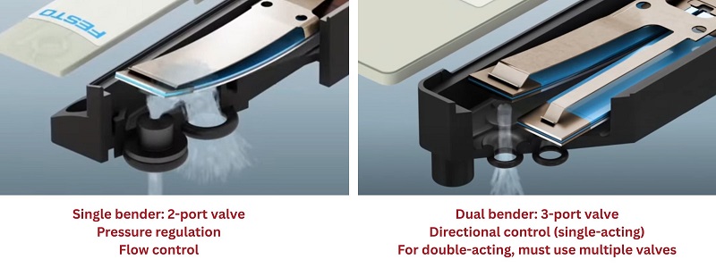
Figure 3. Valves with 1 or 2 benders are used for different purposes. Image (modified) used courtesy of Festo
Directional Control
If we can use a valve to open and close the passage of air, then we already have the makings of a directional valve. Unlike spool valves, which use one moving shaft to route air between 4 or 5 ports, piezo valves are designed with only two benders. This allows the input and exhaust of air. This arrangement works fine for controlling a single-acting cylinder; it’s analogous to a 3-port/3-way valve.
However, if we need to control a double-acting cylinder, we must use two of these valves in tandem. If we wish to truly duplicate a single 5-port / 4-way valve with a single point of air input and exhaust, we must use 4x piezo valves in an arrangement that only allows air in one direction at a time. For electronic enthusiasts, this appears quite similar in flow to an AC rectifier using SCRs!
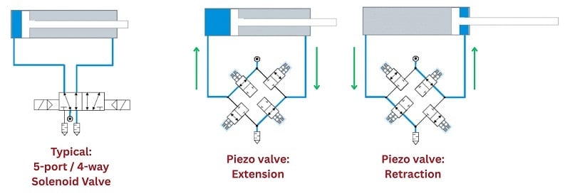
Figure 4. To control double-acting cylinders, a total of four benders must be used in combination. Image (modified) used courtesy of Festo
The bonus feature about these piezo valves in this arrangement is that the directional control and the flow control (ext/ret speed) are controlled at the same time.
Drop-In Replacement? Maybe Not Always
As they say, there’s a time and a place for everything.
For sensitive equipment, like in medical and laboratory environments, it is likely that individual pressure, flow, shutoff, and directional control are all integrated into every branch circuit. In these cases, this piezo valve is a great solution that wraps all of these requirements into one device.
On the other hand, if the goal is simply to provide open-close control for large air cylinders in a rugged industrial environment, piezo valves may not support the required flow rate, and the extra cost of the advanced valves is quite likely not to be recuperated.
It’s exciting to learn more about new technologies and to stay informed about what the future of pneumatic technology might be like!
Related Content