Facebook
 Google
 GitHub
 Linkedin
Add a Dynamic Braking Resistor to a PowerFlex VFD
Dynamic braking resistors stop motors more quickly by converting the rotational energy, but how do we select the correct one and configure a PowerFlex drive to utilize the resistor effectively?
Electric motors convert electrical energy into rotational energy, but what happens when your motor starts converting rotational energy into electrical energy?
This is where the braking resistor comes into play. A braking resistor will use the rotational energy and convert it to thermal energy, like a generator. But how do we size an external braking resistor, and how do we configure the VFD to accept an external braking resistor? Follow along as I walk through the process of adding an external braking resistor to a PowerFlex VFD.
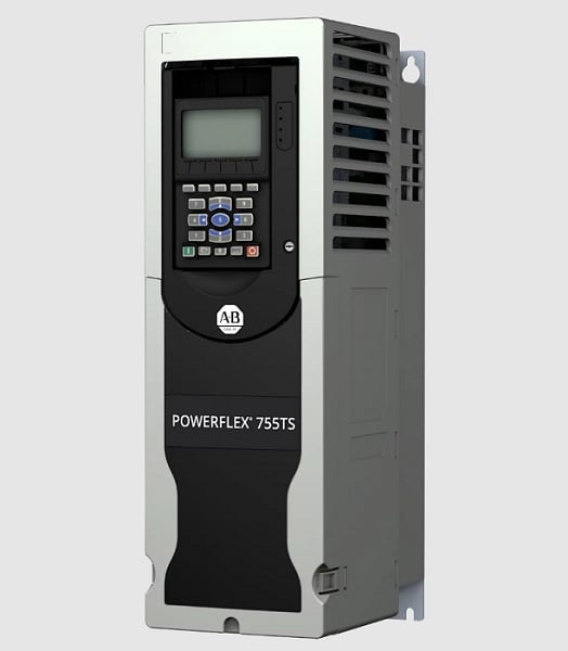
Figure 1. PowerFlex 755TS. Image used courtesy of Rockwell Automation
The PowerFlex Drive Family
The PowerFlex family of VFD is certainly a popular line, but you can add an external braking resistor to virtually any VFD on the market, provided the frame size supports a braking resistor. Make sure to verify the user manual of your chosen VFD. In this article, I’ll focus on the PowerFlex 500 and 700 series drives, but most of the terminology will be similar to other VFD makes.
Selecting The Size Of The Resistor
The size of the resistor is very important, as it must be able to handle the regenerative power from the drive, or the drive will trip its internal safety circuitry. To find the correct resistor size, we must first calculate the peak regenerative power from the drive. We will need the power rating, speed rating, required deceleration time, motor and load inertia, gear ratio, and motor shaft speed. Some of these values can be retrieved from the motor nameplate while others are process-related.
Rockwell gives all the formulas, along with an example calculation, in the PowerFlex Dynamic Braking Resistor Calculator document (page 19). Essentially, we are calculating the total inertia of the rotating system, multiplying it by the angular speed, and dividing by the time.
$$Braking~Power = \frac{Total~Inertia \times Ang~Speed}{Stopping~Time}$$
Depending on your system, this calculation can be very complex or quite simple. The example from Rockwell uses a 10 HP motor that is directly coupled to the load, and they have already figured out the load and motor inertias.
Once the braking power is calculated, we must compare this value to the drive-rated regenerative power, calculated as follows:
$$Regenerative~Power = \frac{DC~Bus~Voltage}{Min~Brake~Resistance}$$
These values are gathered from Appendix A tables in the PowerFlex Dynamic Brake Resistor Calculator document. Once the regenerative power has been calculated, compare the value to the calculated braking power. If the braking power is greater than the regenerative power, the stopping time will need to be increased.
Since this article is about braking resistors, it is assumed the application is periodic, meaning that there will be cycles of time in which the motor is not spinning. To make sure the resistor has enough time to cool down, we also need to calculate the average braking power. The peak power calculated above should be greater than the average power.
$$Avg~Braking~Power = \frac{Decel~Time}{Duty~Cycle} \times \frac{Peak~Power}{2} \times \frac{Rated ~Ang~Speed}{Final~Ang~Speed}$$
You now have all the values necessary to select a resistor from a manufacturer.
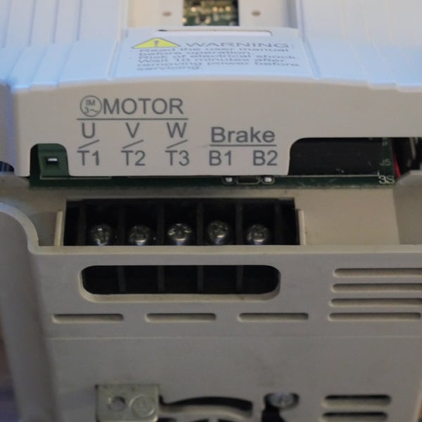
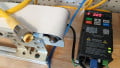
Figure 2. Connection terminals for a brake resistor. Image used courtesy of Control.com
Connecting The Braking Resistor
The PowerFlex drives do not have native thermal protection for external braking resistors so you will need to design a thermostat for the resistor into the motor wiring. The resistor positive and negative conductors are wired to terminals BR1 and BR2, respectively. If the thermostat opens, all power from the motor to the drive will be disconnected, thus preventing a potential fire situation.
Parameterization
The parameters describe the resistor specs and how to direct unused power so that it can be dissipated correctly. Depending on your use of a PowerFlex 700 series or a PowerFlex 500 series drive, the parameters will be slightly different.
700 Series VFD
This series of drives has more options and larger frame sizes, so pay attention to the following parameters.
370 Stop Mode A: Set to 1 to use your determined ramp rate
372/373 Bus Reg Mode A and B: Value 2, 3, or 4 depending on brake type
374 BusReg Lvl Cfg: Leave Default (0)
375 Bus Reg Level: Leave Default (0)
382 DB Resistor Type: Set to 1 when using an external braking resistor
383 DB Ext Ohms: Value of brake resistor in ohms
384 DB Ext Watts: Value of brake resistor in watts
385 DB Ext pulse Watts: If using a brake resistor found in the PowerFlex Dynamic Braking Resistor Calculator document, the pulse watts will be listed. If you are using another brand of resistor, contact the manufacturer for the number of watts the resistor can handle in one second.
426 Regen Power Lmt: Limits the power from the motor to the drive but is only active in Flux Vector control mode
40 Mtr Options Cfg Bit10 (DB While Stop): Enable bit 10 within parameter 40 to enable the internal dynamic brake transistor.
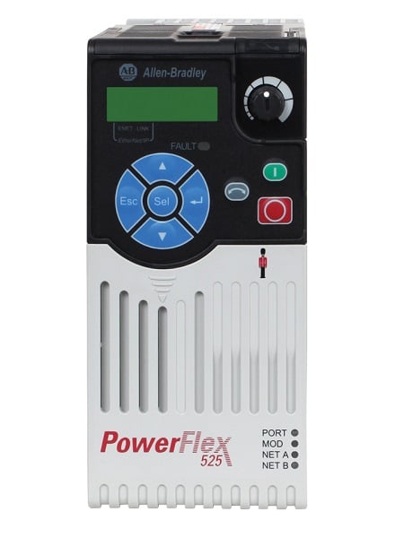
Figure 3. PowerFlex 525 VFD. Image used courtesy of Rockwell Automation
500 Series VFD
The following parameters are used to configure a PowerFlex 520 series drive to use the braking resistor correctly.
P045 Stop Mode: Leave Default (0)
A437 DB Resistor Sel: This parameter is very application-specific.
If you are using a Rockwell Automation resistor, you will want to set this value to 1.
A value of 2 results in no protection to the resistor. The resistor will be used 100% with no duty cycle.
Values 3 - 99 determine the amount of duty cycle the resistor will be subjected to. At the beginning of the braking cycle, the resistor will be on for 10 seconds then a duty cycle of the value chosen will be pulsed to the resistor.
Summary
When the load is enough to free-spin a motor, or if you want to be able to slow down and stop your motor faster than the drive ramp values can handle, then adding an external braking resistor is an effective solution. While there are some calculations required to find the right resistor, the overall process is fairly simple. If you don’t happen to use PowerFlex drives in your application, most of this terminology will still be similar, but even so, always refer to your specific drive’s manual for proper configuration of the brake resistor parameters.