Facebook
 Google
 GitHub
 Linkedin
Adding Remote I/O to a PLC Project: Synergy Logic Meets CompactLogix
In this tutorial, we add remote I/O to a Studio 5000 project using Modbus TCP and the new SLM System from Synergy Logic, which promises to simplify the integration. We’ll see how it lives up.
A big buzzword around control system circles these days is ‘distributed,’ and it’s often tacked onto motor drives, I/O units, and network gateways. It means that we can install all of the field ‘stuff’ far away from the control ‘stuff.’ In other words, it’s all networked remotely to the PLC.
Today, we’re checking out a modular I/O rack, designed to be installed remotely, but promising to provide an easy, simple integration experience. We’re going to put this to the test and see how much effort we must provide to read and write both discrete and analog information from a CompactLogix PLC.
Hardware Overview
The SLM system from Synergy Logic is a chassis-free, modular remote I/O system. It consists of only one option for the bus coupler: Modbus TCP. This protocol is fairly universal (as much as possible in the world of automation).
This system contains the bus coupler, a 16x relay (discrete) output card, an 8x discrete input card (simulated with switches), a 4x thermocouple input card, and an analog combination 2x in/2x out card.
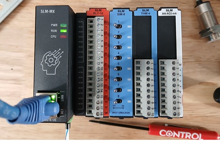
Figure 1. The complete remote I/O setup.
Next, we only need the CompactLogix PLC, the programming computer, and a couple of standard network cables to link them. Beyond these basics, the rest of the automation system is entirely up to your imagination.
1. Connect the SLM
The SLM-MX bus coupler only requires 24 VDC and an Ethernet connection to the PLC for final operation. For the easiest benchtop setup, place the SLM, PLC, and the programming PC on the same network.
From the factory, the SLM-MX will likely not be on the same subnet as the PLC, so the next step will be to set the IP address of the SLM-MX. This is the only configuration that will be required.
2. Configure SLM Network Address
Inside the SLM-MX, DHCP is enabled by default. However, if you are connecting to the PLC and a laptop, a DHCP server isn’t usually a standard option, so we must take note of the default IP address: 169.254.10.10.
Change your laptop’s network configuration to a subnet that is similar, perhaps with the address of 169.254.10.2. You will now be able to change the IP address of the SLM to communicate with your PLC.
Download and install the MX configurator software. Open the software, type in the default IP address of the SLM, and press the green Connect button.
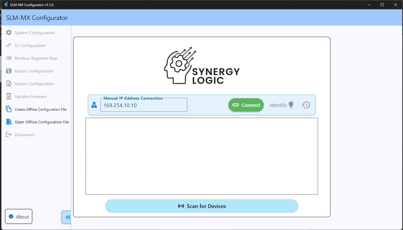
Figure 2. Configuring the remote IO.
When the SLM system is identified, click on the bus coupler and ‘Edit Configuration.’
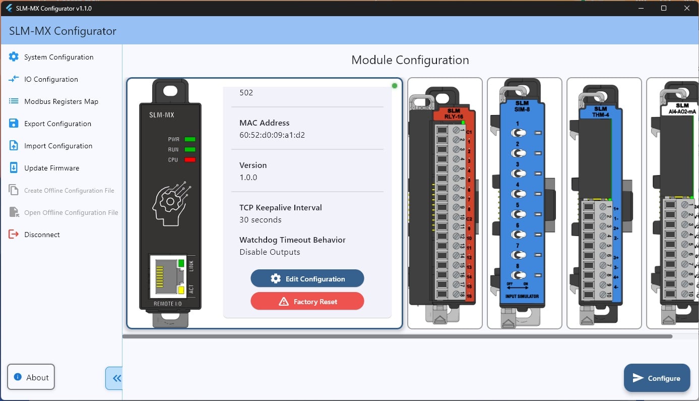
Figure 3. Identifying the SLM-MX.
Set your parameters and click 'Save.'
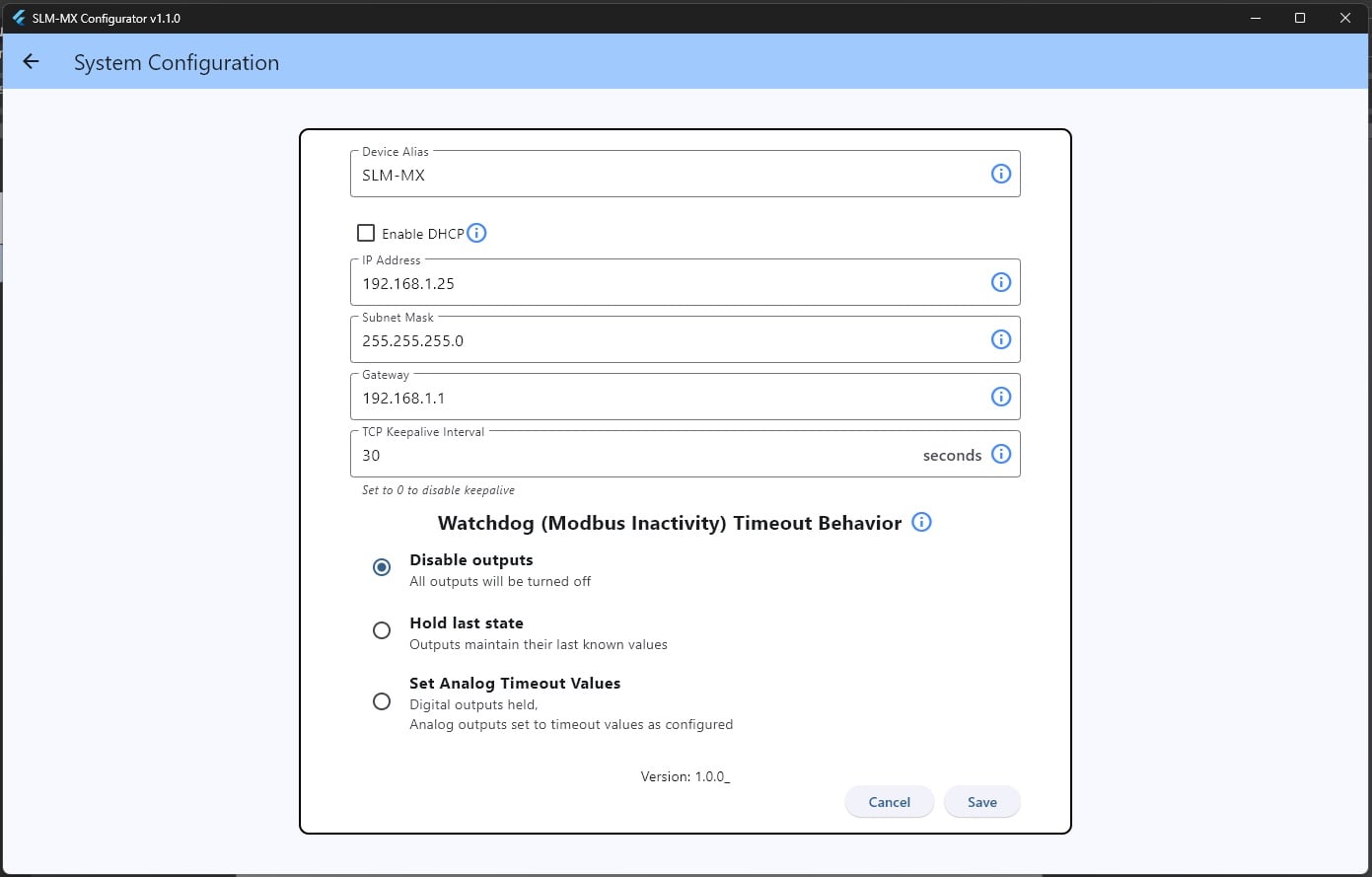
Figure 4. Setting the IP address.
On my benchtop setup, my PLC and computer are both on the local 192.168.1.xxx network, so this is my chosen IP address.
The SLM configuration is now complete.
Sidebar Notes on Modbus Mapping
While you have the software open, you can check the Modbus addresses to keep them in mind for later. Click ‘Modbus Mapping’ on the sidebar and all modules will be displayed. This is standard Modbus addressing, where the prefix determines the type: 0xxxxx is for coils, 1xxxxx for contacts, 3xxxxx for register (analog) inputs, and 4xxxxx for register (analog) outputs.
This hardware setup is fairly easy; for example, the simulator input contains addresses 100001-100008. Since 1xxxxx always refers to inputs, we only need to note the final address number, 1-8. If I had a second card, it would show 100009-100016, referring to inputs 9-16.
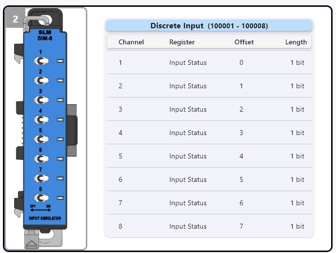
Figure 5. Modbus IO map for this module.
What this tells us is that when we run the Modbus transactions for this module later, we just need to point at the SLM-MX IP address and tell it we want to ‘read the first 8 discrete inputs.’
That’s it.
Don’t overcomplicate it.
3. Install Rockwell’s Modbus Client AOI
Studio 5000 does not have a built-in Modbus read/write function block, but there is a simple solution. Go to the Rockwell support site and download the pre-built Modbus TCP AOI. Extract this folder.
Open a recent or new Studio 5000 project, but this is actually an L5X file type which is a logic package, so don’t immediately ‘Import AOI.’ Instead, add a rung where you wish to perform the Modbus read/write and ‘Import Rungs’ in the ladder routine. Choose the “TCP Client” logic file.
The rung will now contain a single instruction capable of reading and writing many Modbus instructions all in one command, with the default name of “Client_01.”
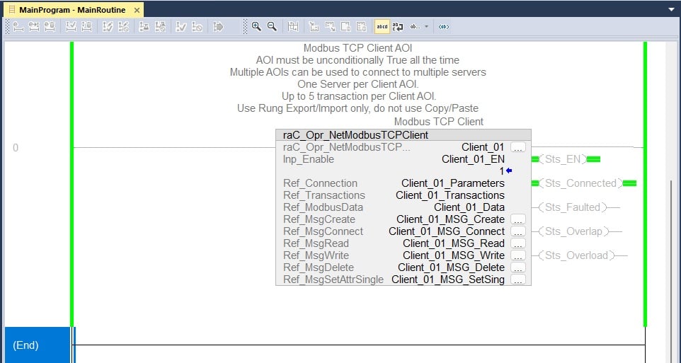
Figure 6. Imported Modbus Client logic rung.
4. Configure the Modbus Function Instruction
This function requires a little bit of configuration. In this example, we’ll read the simulator discrete inputs and write to the relay outputs.
IP Address of the SLM-MX
First, we need to set the remote IP address. In the controller tags list, expand Client_01_Parameters -> .DestAddress. This is a STRING data type, so double-click and add the IP address between the delimiting quote marks.
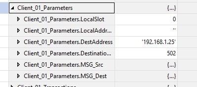
Figure 7. Setting target IP address.
Read the Inputs
There are several available transactions, and we’ll use one for the inputs and another for the outputs.
For the inputs, use the image below as an example.
- Enable the transaction
- Change the polling delay interval (if you want)
- Transaction type is 2 (more about Modbus function codes here)
- Beginning address is a bit tricky; address 0 actually refers to the starting Modbus logical address of xxxxx1. So we choose a starting address of 0, and it will retrieve address 100001. If you want to understand this number shift, search online for “Modbus zero-based addressing.”
- Count is 8, meaning we’ll read 8 consecutive Modbus inputs.
- Local Address is the starting array index of the DiscInputs tag where the values will be stored. Leave this 0 for now, but if you needed to read 8 inputs here, and then read another 8 inputs later, you would want to store those new ones with a starting address of 8 so they don’t over-write these values.
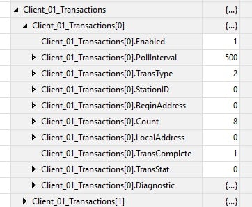
Figure 8. Transaction for reading inputs.
Write the Outputs
The transactions for a “multiple coil write” action will look quite similar. This time, the transaction type is 15 (multiple coil write) and we are counting 16 consecutive terminals, because it’s a 16 relay output module.
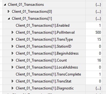
Figure 9. Transaction for writing to outputs.
Download the code to the PLC, and set the Main rung instruction Inp_Enable to 1.
5. Read/Write the Data
Flip a few switches on the input module and open the Client_01_Data DiscInputs array tag. You should see the Bools reflecting the real-world state of the module.
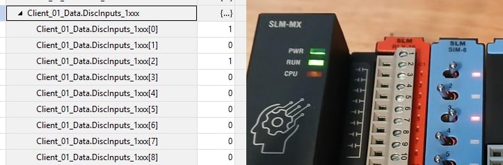
Figure 10. Verifying inputs - they work!
Similarly, open the Coils tag and place a couple of 1 values into a few spots. The relay module should energize accordingly.
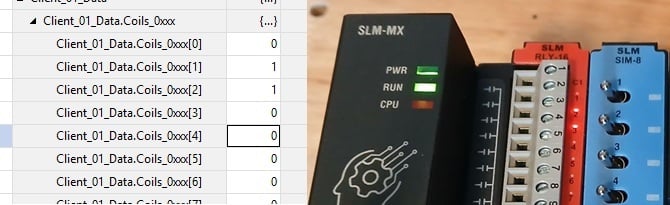
Figure 11. And the outputs - they work too!
Next Steps
With this project, we can now easily read and write to the discrete coils, and the registers are the same method, except the transactions require codes of 04 (reading inputs) and 16 (writing multiple outputs), and going to the InpRegisters and HoldingRegisters tags.
I also like to set up an IO mapping routine in the logic which can create easier names for the separate modules in the remote I/O block. But this mapping discussion is for another time and another place. For now, we have a working program!
All images used courtesy of the author.