Facebook
 Google
 GitHub
 Linkedin
All About The Legendary Stack Light
The stack light has a simple but powerful purpose: to report the status of the equipment. Follow along as we take a deep dive into the venerable illuminated signal tower.
The factory floor is a busy place with multiple machines making noise and flashing lights, so it can be difficult to determine the status of any one machine.
Machine builders solve this challenge by adding a stack light to their equipment to signify the status of each cell or zone. But what do the different colors mean, and is there a standard use for each color segment of the stack light?
The following article will expand on the functionality of the trusty light stack, providing insight into different models, connection methods, and their respective functionalities.
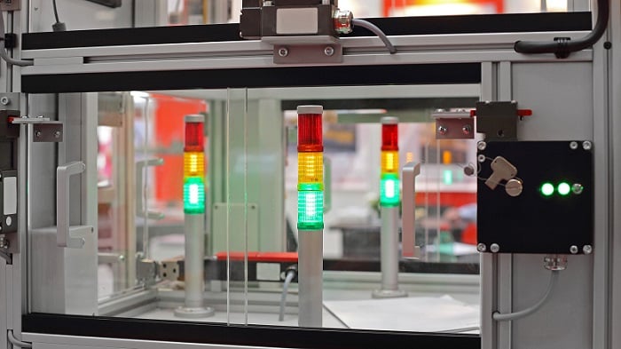
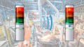
Figure 1. Stack lights showing the status of equipment. Image used courtesy of Adobe Stock
Red, Green, Yellow: Not Just For Traffic Lights
A standard stack light is often made up of one or more segments (often called tiers) of colored light, with an optional buzzer. Each color can be given a specific meaning as to the current status of the equipment. Additional meaning can be given to each color by flashing at a frequency that operators can see.
PLC programming languages fall under the IEC 61131-3 standard, and manufacturers of control systems need to adhere to this standard if they want to be compliant. Stack light colors, in contrast, do not fall under any standard, so it is up to the end user to define what each color means and how to indicate the machine status.
The following list includes some common meanings for the standard colors:
Red - Equipment is faulted (flashing) or the control power is off (solid)
Yellow or Orange - Caution or warning; the machine may still run, but there is something that requires attention. Bowl feeders will commonly trigger a warning when they need to be replenished.
Green - Equipment is running in auto mode without errors. It can also indicate that the system has control power and is ready to start production. Flashing the light will help denote the two different functions.
Of course, these are not the only available colors; there are other fixed color segments, and the advent of RGB LED segments can yield millions of subtle variations.
Blue - Often used as an alternative status. This could mean something similar to a warning, or it might be used with control power. It can also be included as a multi-color variable-level indicator.
White - Another color that is often used for special states that are not found in all equipment.

Figure 2. Typical red, yellow, green light stack showing the status of an automated cell. Image used courtesy of Adobe Stock
LED or Incandescent?
A common question these days is the choice of bulb technology. Most stack lights are shifting to LEDs, for a few reasons. They emit less heat, and therefore last longer and consume less current, which is beneficial for power conservation. They are also small, which means several colors can be placed next to each other in the same element, or an RGB can be used.
Most LEDs are soldered directly onto a circuit board, so when the segment finally does fail, you must purchase a new segment. Incandescent, on the other hand, is usually just a bayonet-style bulb, so replacement is far cheaper.
LEDs emit a specific color, so you need to stock replacement bulbs for each color. Incandescent bulbs all emit a pale white/yellow color, so the segment color is determined by the plastic shell. Therefore, a company needs only stock one universal P/N of replacement bulb for all applications. A huge saving in cost and replacement headache.
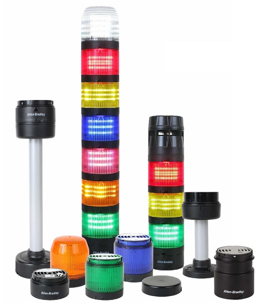
Figure 3. Standard modular light stack tiers and mounting options. Image used courtesy of Rockwell Automation
Customization and Types
Different manufacturers have different trade names for these stack lights. A few variations might include light towers or tower lights, andon lights (andon is a broader term for a manufacturing indication system), indicator lights, and signal lights. You may know other perfectly applicable names.
Many different suppliers offer various styles of light stacks; some are fixed in the color segment orientation, while others can be assembled in different configurations. Some versions require individual wiring for each segment, while others use industrial protocols such as IO-Link to allow for dynamic parameterization and customization. A popular add-on function is a buzzer that can sometimes be adjusted for volume and frequency.
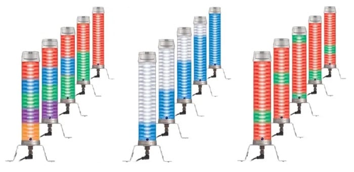
Figure 4. Several of the color options permitted by the use of fieldbus protocols and RGB segments. Image used courtesy of Balluff
It’s All About Location
After you’ve spent time developing your status color and programming each status, you will want to make sure operators can see your stack light.
Some lights are mounted on a pole, to be set above the high point of the machine. Other lights are side-mounted, to be fixed to the most visible side of the equipment or a nearby wall. Wherever you place the light stack, make sure operators can see it from multiple angles. You don’t want to place it too high, because it will be out of sight to the operators working on the equipment, and too low will affect maintenance staff walking by.
If using a buzzer, ensure it is configured to sound different from other buzzers and alarms, and ensure that it is loud enough to be heard over ambient noise.
Control Signals
There are several ways to connect the stack light to the rest of the control system.
Some lights include a long cable with exposed wires at the end, each one identified by a color. The wire colors do not always correspond to the light color, but sometimes they do. Other models provide an industry-standard M12 connector, each tier color matched with a numbered position inside the connector.
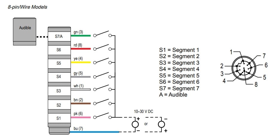
Figure 5. An example wiring diagram for a standard segment light stack. Image used courtesy of Banner Engineering
Digital I/O Wiring
A common version is the discrete version, which uses standard 24 VDC or 120 VAC current to drive each color or buzzer. A normal diagram includes a separate wire for each segment, or for each color if it’s a non-modular stack. A common wire will provide either ground (if it’s an NPN/sinking load) or a common 24 volts (if a PNP/sourcing load).
Fieldbus
Fieldbus light stacks use popular industrial protocols to signal different colors and set various parameters. With these functions available over the network, special functions can be enabled dynamically as the state of the machine changes. For example, the Balluff SmartLight stack is made up of multiple segments that can be configured dynamically to be different colors. This particular light stack can not only show the status of the machine but also indicate the level of the reject bin by illuminating each segment from bottom to top as the reject bin is filled.. A function that would require additional hardware with a standard light stack configuration.
The Legendary Light Stack
The light stack has a simple but effective purpose: to display the status of the equipment. While the overall purpose of the light stack hasn’t changed over the years, the technology used in the light stack has. From incandescent bulbs to LEDs, and from discrete wiring to fieldbus communications. The method of how the status is indicated might change over time, but the message remains the same.