Facebook
 Google
 GitHub
 Linkedin
Common Control Concepts Used in Robot Motion Planning
Learn about motion planning for robotic systems and arms including tips on math concepts and space configuration.
Robotic arms have to move from one position to another regularly. As mentioned in a previous article, robotic arms are not simple contraptions. They are complex systems with multiple moving parts, different types of joints, and motion axes.
What is Motion Planning in Robotics?
Motion planning is the process of mathematically calculating the path from starting point to finishing point. Various types of robotic arms have different methodologies to calculate the path according to the types of motion and configuration. This helps identify the shortest path avoiding obstacles, walls, and other constraints the configuration space might have.
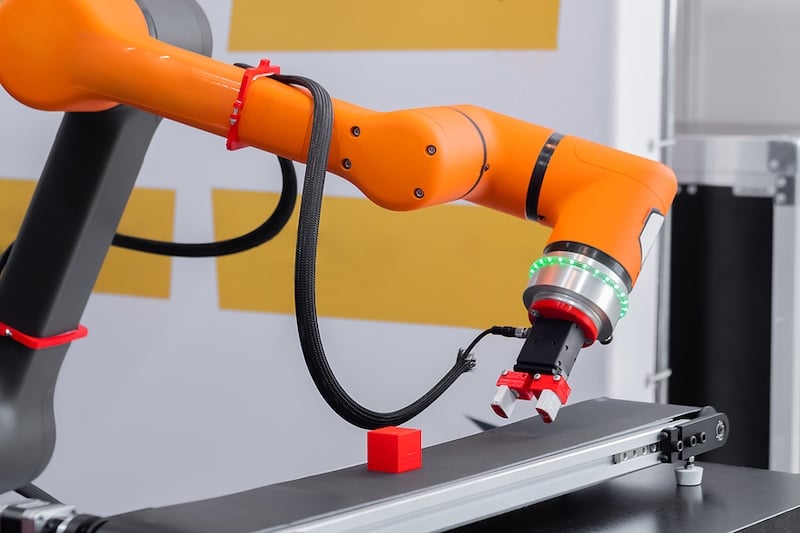
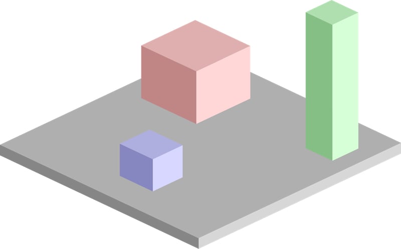
A pick-and-place robotic clamp arm manipulator moving blocks.
The tools one will need to solve the mathematical problem depend on the type of robot.
- Cartesian robot - Cartesian coordinate geometry
- Cylindrical robot - Cylindrical coordinate system
- Spherical robot - Polar coordinate system
- Six-axis robots (articulated robots using kinematic structure) - Forward and inverse kinematics
Mathematical Concepts Involved in Motion Planning
Though different mathematical tools are used to plan a path for the robotic motion for different robots, some concepts are the same for all the scenarios.
A simple motion planning problem would be to plan a continuous path between the starting position A and the desired position B. There would be constraints attached to that. The arm should not collide with any walls or objects while moving to the desired position.
This article will address the common concepts involved in motion planning, using a gantry robot as an example. For mathematical calculations, space is considered Euclidean space, and the robots are considered Euclidean groups.
Considering the Configuration Space
The parameters that define the configuration of a robot in a vector space are the configuration space for the robot. The parameters are mathematically constrained generalized coordinates that can define the configuration of a robot.
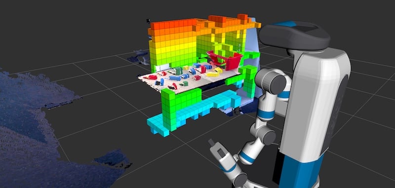
A robot utilizing motion planning technology. Image used courtesy of Fetch Robotics
Robots with kinetic chains have multiple joints that can move and rotate. For each generalized coordinate, the robot can have multiple configurations of the positions of each joint. The configuration space will depend on the perspective of calculations. Configuration space can be from the perspective of the whole robot with its many joints.
In that case, configuration space consists of the position and location of all the linkages of the robot. Another way to think about the configuration space is from the perspective of just the robot's end-effector without considering the rest of the robot. This only applies when one has considered the position and location of the end-effector.
For a two-dimensional space, the configuration space is represented as:
C = R2
That is, it can be represented using two parameters (x, y).
For a three-dimensional space, the configuration space is represented as:
C = R3
It can be represented using three parameters (x, y, z).
Two-dimensional space that has rotation in addition to translation motion is represented as:
C = R2 X SO(2)
Where SO(2) is the special orthogonal group of two-dimensional rotations.
Similarly, three-dimensional space that has rotation in addition to translation motion is represented as:
C = R3 X SO(3)
Where SO(3) is the special orthogonal group of three-dimensional rotations.
In general, for a robot with no revolute joints, the configuration space can be represented as:
C = [R3 X SO(3)]n
Free Space
The configurations of the robot for which collisions are avoided, the area beyond edges are eliminated, and forbidden spaces are avoided cumulatively from the free space, Cfree.
Due to the nature of free space, it is very resource-consuming and ineffective to calculate free space. That is the complete possible configurations for the robot in the given space. Therefore, it is done the other way. A given configuration is tested whether it lies within Cfree.
Target Space
It is the desired position for the robot to reach. The location and the robot's position are included in the representation. Depending on the use case, only the end location may be factored in. The position of the robot's linkages can be anything as long as the location is valid. The robot has to traverse from current space to target space through the free space.
Obstacle Space
It is the area where the robot is not allowed. It could be due to obstacles, or because it is beyond the periphery of configuration space, or forbidden due to other constraints in the configuration of the robot.
Cobs = C - Cfree.
Motion Planning For a Gantry Robot
Now, let us consider how motion planning is executed for a simple two-dimensional gantry robot. Gantry robots are linear in nature. They only have translation motion and do not have the capability for rotary motion. This makes the Euclidean space for such a system a simple two-dimensional coordinate system, a cartesian coordinate system.
The gantry robot is always on metal rails set up on scaffolding. It can accomplish only linear motion along the two axes, the x-axis, and the y-axis.
The area which it can traverse can be represented as a rectangle. In the initial step, let us consider that the robot's end-effector can be represented as a single point in the space. There are some obstacles in the configuration space too. A pictorial representation is given below.
Example of a robot's workspace. Image used courtesy of Simeon87
This is a space with three obstacles. The entire space, including the obstacles, constitutes all possible configurations of the robot and is the configuration space, C. The top view of the configuration space is like the image given below and is a two-dimensional plane.

The dark grey rectangles represent the obstacles, and the rest of the space is free space available for the robotic arm to move in. Image used courtesy of Simeon87
Now imagine an end-effector has to be moved from one position to another. Let the blue rectangle show the initial position, and the red rectangle show the final desired position of the end-effector.
The end-effector is not a single point, but it is a thick tool in a rectangular shape. The black dot at the lower corner of the effector is taken as the point that is to be moved. When the width and height of the effector are to be considered, and additional space has to be left around the obstacles and the periphery. This way, no part of the end-effector touches it. It is indicated by the light gray portion in the image.
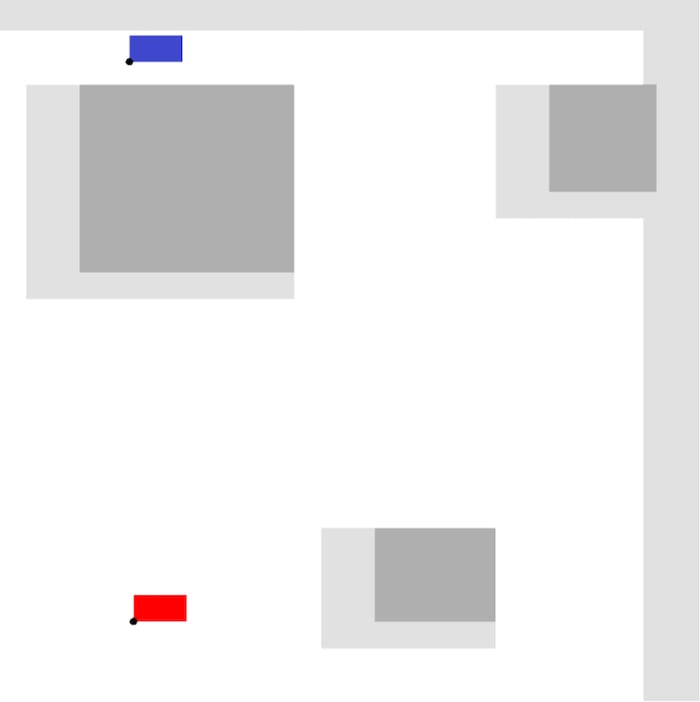
Here:
C = The complete space in the image
Cobs = The light grey and dark grey area in the image
Ctarget = The red area in the image
Cfree = The white space in the image
Since gantry robots are linear, the end effector can move only in straight lines. The engineer can use many techniques to engage and calculate the path between the current space of the end-effector and the target space. Using a pathfinding algorithm, one can find the optimal path to be taken. Some of the algorithms that are commonly used are:
- Grid-based search
- Interval-based search
- Visibility graph
- Cell decomposition
- Minkowski sum
- Artificial potential field
- A* algorithm
- D* algorithm
- Probabilistic roadmap
These algorithms can handle the constraints of the configuration space and output an optimal path that can be taken. The next part deals with geometric and transformation matrix-based solutions for kinematic chains.
Motion planning, path planning, or navigation problem involves planning the configurations required to move from one position to another. Motion planning as a whole can be used in various types of robots and robotic arm solutions.