Facebook
 Google
 GitHub
 Linkedin
Communication and Power Redundancy for Control Devices
Power and control interruptions are, at best, problematic. In some applications, it’s catastrophic. Learn about redundancy for the system, power supplies, control devices, and network topologies.
Industrial control systems, which consist of control devices, network media, applications, and protocols, must provide services without interruption. The question arises as to why we need redundant hardware in critical processes such as monitoring and controlling generation, transmission, and distribution systems.
The answer is simple: for the supply of electricity and control without any interruption.
System-level Control Redundancy
Through redundancy, one fragment of the system is used for the operation, while the other is on standby. When the active processing element fails, a switchover to the standby can occur without causing any operational interruption. It is important to note that when we decide to install redundant hardware, we must ensure that the hardware has that specific capability.
From the operator's point of view, let us present a straightforward example of distributed redundancy unit control. In a power generation plant, different control (start/stop) modes are available, like local-manual, local-auto-state, and remote-auto modes to start/stop the unit from different locations. Using these modes, distributed control and redundancy are both possible. For example, If remote operation is not possible from a control center, then local control is available from the LCU panel to start/stop the system.
The redundant topology usually comprises two CPUs/PLCs with redundant power supply modules, a redundant network route, and an online/stand-by server with HMIs at the control center level.
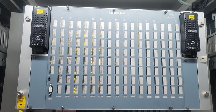
Figure 1. The Siemens controller SICAM AK 1703 ACP is equipped with redundant power modules.
Redundant Power Supply Modules
Industrial control hardware enclosed inside the panels, such as PLCs/RTUs/controllers, often operates on a 24 V DC system. Utility control and monitoring of power, transmission, and distribution require reliability and performance, and unexpected power loss in control devices could be disastrous. Redundant power supplies are installed for control elements like the digital governor and excitation system etc.
As in Figure 1, the Siemens SICAM AK 1703 ACP, which is installed in the hydropower plant to control the generating units, is supplied with redundant power supplies PS-5620 (110 to 220 VDC or 115 to 230 VAC), which are slotted into upper left/right slots into the mounting rack from the front. The types and numbers of power supplies depend on the requirements and mounting rack. In this scheme, if the primary power supply fails for any reason, the secondary or backup power supply will deliver the power to the control device.
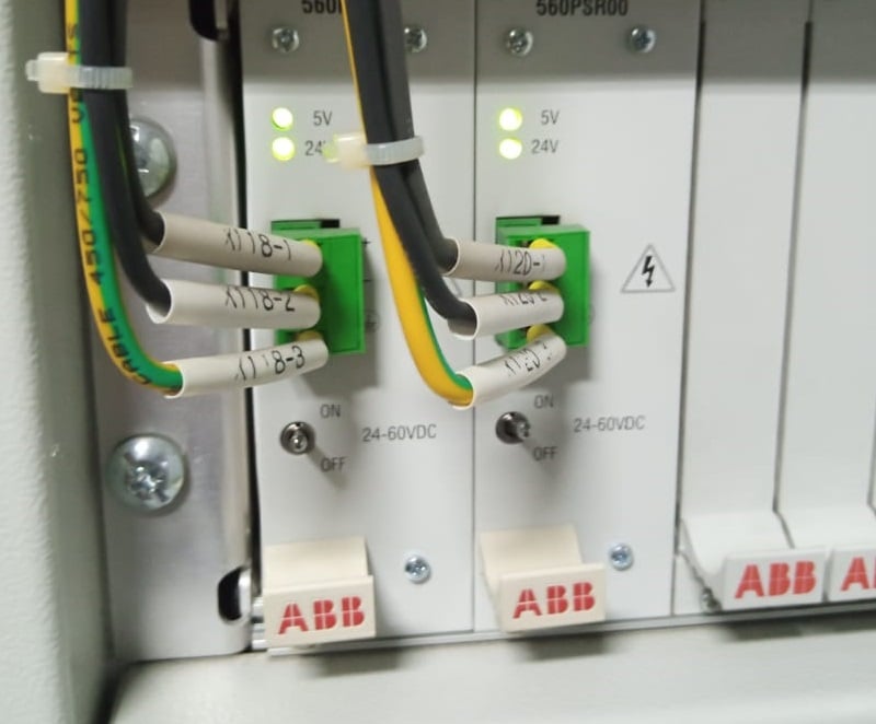
Figure 2. A redundant power supply unit (input voltage 24-60VDC) installed in the RTU 560 rack.
Redundant CPUs
The redundant CPUs mean the presence of one or multiple CPU pairs. Everyone knows the standard, traditional method of PLC execution, in which a single PLC or a single CPU in the plant is connected with several other components like I/Os to transfer the plant data to the upper layers.
The upper layer may be the front end, control center, or HMI. The PLC also sends commands to physical objects like actuators, breakers, pumps, etc. The failover process happens uninterrupted for crucial industries like power generation, oil, gas, and water treatment, ensuring system availability in the redundant CPUs scheme. The hardware configuration and programming have been done in such a way that under normal situations, one of the CPUs is the ‘master’ which controls the system, and the other one is the reserve. If the master CPU detects an internal, the other one takes control and becomes the master.
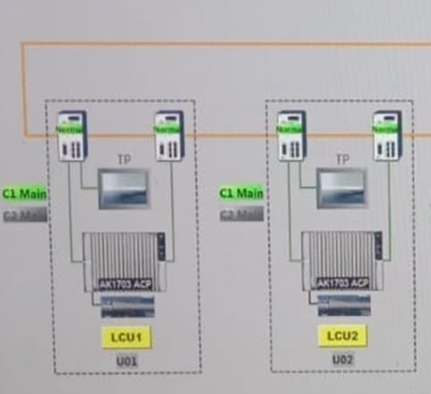
Figure 3. AK1703 ACP is equipped with two CPUs (C1 Main and C2) installed in the LCU1 of Unit #1.
The operating modes of the critical devices within the system are defined as Online/Active and Standby. As in Figure 3, one CPU (C1 Main) is active and online, while the other CPU (C2 Main) is in standby mode.
Dual Computers/Server (Online/Standy modes)
The dual or multiple servers are running mission-critical applications, used to maintain high system availability. The main computer subsystem includes redundant devices (servers/workstations) so that the failure of one server does not cause the subsystem to fail. During normal operation, one main server, such as SCADA server-A, domain controller-A, or historian server-A, running on multiple physical servers or running as a virtual machine on a single physical hardware host, is assigned the online mode and performs all the functions. The other of the two servers, like SCADA server-B, domain controller-B, or historian server-B, are maintained in readiness for immediate takeover, or standby mode.
The following functions are the responsibility of the online system:
- Maintain the currency of the online database
- Maintain control system error log
- Control switchover to standby facilities
- Monitor the status of standby equipment
Device Supervision and Status
The latest control systems provide continuous automatic device supervision depending on their supervision status. The supervision status of each monitored device in the system is maintained, and it has the following supervision statuses:
In Service:
The device status is manually set by the control system equipment to designate the device as available for use by the system. In-service devices are automatically supervised.
Out of Service:
The device is not available for use by the system and the out-of-service devices are not automatically supervised.
Operable:
In-service devices are assigned this status by the system when no failures have been detected.
Inoperable:
In-service devices are assigned this status when failures are detected during normal supervision. Any change in device supervision status records the events related to them.
Redundancy in Communication Network
As stated above, most electric power plant networks are critical, so the communication network needs to be reliable and restored as quickly as possible. So, as usual, the requirement is to avoid signal point failure.

Figure 4. A typical redundant network called HSR (High-availability Seamless Redundancy) deployed for SCADA systems.
The common redundant LAN topology for control systems are dual LAN, ring topology, and parallel redundancy protocols (PRP). Often, the tough environment in power plant applications poses unusual provisions in terms of network availability. Redundant networks are designed in the automation field because they require alternate paths to switch over in the event of an error which will cause data delays and loss. In PRP, each device is connected to two separate LAN networks and the data is transmitted in parallel via both networks. In the event of failure, the data packets reach the destination without any delays caused by switchover, reconfiguration, and reboot time.
Control System Redundancy
There really is no industrial application where failure is unimportant, but sometimes, instant system redundancy is more critical than others. Redundancy is an important consideration for the high-level control system architecture, as well as for the individual devices like the CPU, power supplies, servers, and network protocols/technologies, and care must be taken to understand each challenge and apply the right solution.
Related Content