 Facebook
 Google
 GitHub
 Linkedin
Customizing the Connections: Guide to Terminal Blocks - Part 2
Regardless of how a terminal block operates, the proper form factor and function must be chosen for each application. What kind of terminal blocks are offered for various tasks?
Previously, in Part 1, we investigated the actuation styles of modern terminal blocks, including screw, spring, and insertion force. No matter what tools and techniques are required for each block, the design should call for the proper form factor. Terminal blocks are defined by how many levels they occupy, and what connections and devices have been integrated to enhance operation for certain tasks.
As before, my thanks to Hannah Witopil, the Product Manager of Terminals in the Cabinet Products division of Weidmuller USA, for supplying me with a sample of terminal blocks to illustrate many of the available options and operation methods.
Level/Distribution Structure
The choice of activation style (screw, lever, etc.) may come down to personal preference, but the purpose of the terminal block is dictated by the panel project. Some signals must be passed only to one destination, but power/ground connections are often distributed to several destinations. To accommodate these needs, there are many choices for levels and distribution types.
Levels
The level structure is like stories in a building. Multiple tiers extend from the top of the main block base, providing access to more connections in the same horizontal footprint. Terminal blocks exist in single-, double-, and triple-level variants. There may be several connection points per level.
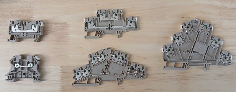
Figure 1. Left to right: single-level, double-level, and triple-level terminal blocks. My thanks to Weidmüller for their generous device contribution for editorial use.
Distribution
Signals and power are treated very differently in control systems. Signals to and from I/O devices are meant only to join that one device to one terminal on the controller. This one-to-one connection means that only two of the terminals on a block should connect through the block. Look back at Figure 1, and examine the blocks on the far left and far right of the image. On the far left, a single-level block, like the ones, transmits only a single signal. Likewise, the three levels of the far-right block each transmit one and only one signal. This terminal block may provide power, ground, and the signal for one sensor while only consuming a few mm of the DIN rail.
On the other hand, look closely at the double-level blocks in the image above. You may notice that inside the 8-terminal block in the lower-center of the image, a metal bar creates a jumpered path between the upper and lower levels. This actually bonds all 8 terminals and creates a single voltage for the whole block. Some terminal blocks may appear identical on the outside, but only a small difference in part number can tell whether the levels are internally bonded or not.
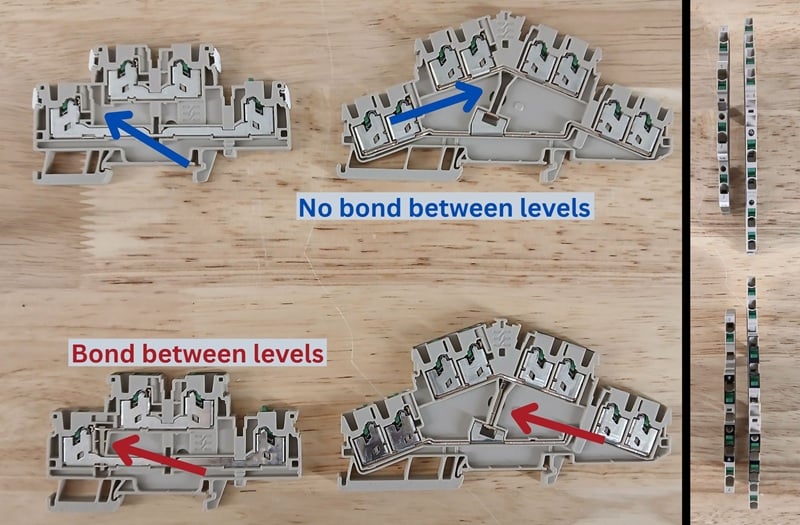
Figure 2. Similar terminal block families, one with and one without an internal bond. For these Weidmuller blocks, the bonded model contains a “VL” appended to the part number, and the top is marked with a unique black ink indicator (right side). Image used courtesy of the author
Jumpers
Since we’re on the topic of joining voltage potentials across terminal block levels, there is an external accessory that accomplishes the same task: the jumper. Some terminal blocks use jumpers that screw down into the top of adjacent blocks, while others press securely into place. Most jumpers have a maximum current capacity that exceeds even most robust industrial power supplies, but still keep the ratings in mind when installing a long row of jumpers that may carry a significant amount of power.
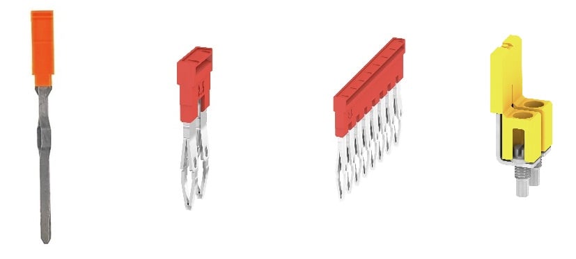
Figure 3. Jumpers include long models for linking multiple levels in a single block, while side-by-side models join adjacent blocks. Image (composite) used courtesy of Weidmüller
Accessorizing Your Blocks
There are many special-purpose terminal blocks, usually with some additional components installed inside. These include fuses, diodes, resistors, and disconnect switches.
Fuses
Fuses are often installed into the top of the terminal block via a removable flap or a pivoting gate. They mostly accommodate small tubular glass fuses. Since the rating of a fuse is dependent on the branch circuit, the installer needs to select their own fuse with specific voltage and current ratings.
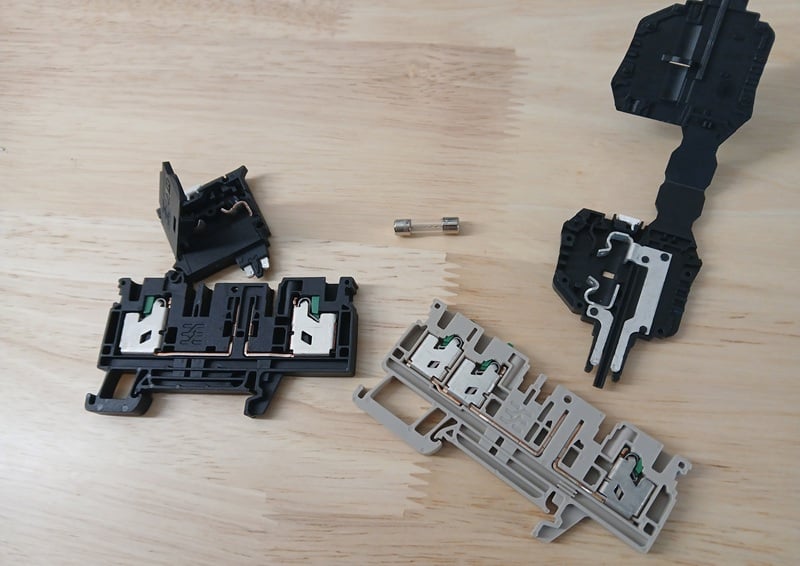
Figure 4. Fusible terminal blocks. Image used courtesy of the author
Diodes
Diodes serve two purposes. First, they protect field devices from accidental crossing of +/- connections, only allowing power when properly connected. These terminal blocks have one or two diodes connecting the left and right sides of the block. Second, they protect controllers from inductive flyback from coil-based loads. These diodes may be installed in series with a single level of a terminal, or placed as a link between the top and bottom levels of a terminal block.
There are many configurations of diode protection, so be sure to verify the exact part number and examine the circuit diagram in the datasheet prior to installation and power-up.
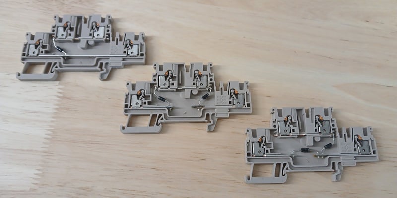
Figure 5. Diode terminal blocks: flyback voltage protection (top-left), parallel signal connection (center), and a combination of polarity and flyback protection (bottom-right). Image used courtesy of the author
Resistors
Resistors are meant to limit the flow of current to a load device. These terminal blocks are often used in series with LEDs and occasionally with sensors that require resistors to convert between voltage and current analog signals. Many of these terminal blocks offer removable resistor slots, so a custom component value can be inserted.
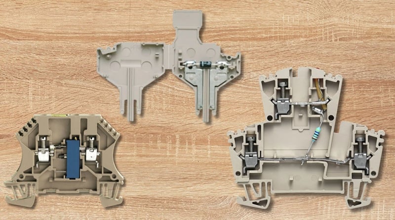
Figure 6. Components like resistors, potentiometers, and others can be added to flexible, customizable terminal blocks. Image (composite) used courtesy of Weidmüller
Disconnect Switches
Some terminal blocks provide a handy method of de-energizing part of a branch circuit without disconnecting wires or turning off the entire power supply. While this may be convenient, disconnects come with a warning: when the circuit is active, each time the switch is opened and closed, a small spark or arc can occur, damaging the terminal block and causing carbon resistance on the metal plate. Try, when possible, to use the disconnect only when power is already removed.
Some of these disconnect switches can be removed and replaced with fuse or component plugs for even more flexibility.
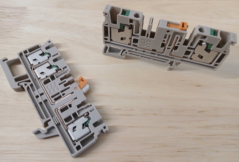
Figure 7. The orange handle indicates a disconnect switch on the top of this terminal block. Image used courtesy of the author
Guide to Terminal Blocks
On the surface, terminal blocks seem quite simple. But an investigation under the hood reveals a wide variety of shapes, styles, and connection methods. No wonder that so many engineers have personal preferences and enjoy learning about new, innovative technology that improves panel wiring in ways that others might not even notice!