 Facebook
 Google
 GitHub
 Linkedin
Securing the Connections: Guide to Terminal Blocks - Part 1
UL guidelines dictate specific types of wiring connections in control cabinets, and terminal blocks are usually chosen to fit the bill. What kinds of terminal blocks exist, and how do they work?
Control panel assembly shops are well acquainted with the guidelines that dictate construction as well as the devices that are approved to fit within those guidelines. One of the most common cabinet devices is called the terminal block, a secure connector used to route electrical power and signals, even under extreme conditions.
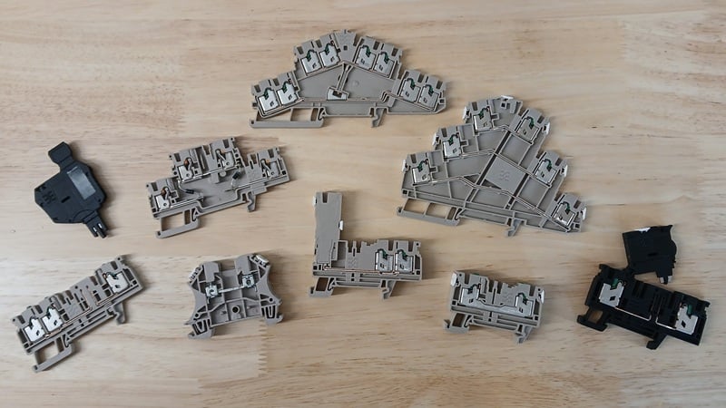
Figure 1. Terminal block varieties, and my thanks to Weidmüller for their generous contribution for editorial use.
Why Do We Need Terminal Blocks?
Two design paths have shaped the physical construction of terminal blocks.
The most important is the history of logical, practical experience from thousands of engineers who have installed and repaired cabinets. This experience has led to innovative designs that provide quick and intuitive actions, while at the same time ensuring that every connection is secure, even when a machine is vibrating.
The second design path is shaped by regulations, including the UL 508 standard for control panel design. All designs must not only work well in theory, but they must prove their ratings through appropriate testing. Therefore, all certified terminal blocks should be trustworthy for long-lasting designs.
Actuation Technology
I would like to give a special shoutout of gratitude to the engineering team at Weidmuller, one of the leading companies in wire connection technology. Hannah Witopil, the Product Manager of Terminals in the Cabinet Products division of Weidmuller USA, provided me with a sample selection of common terminal blocks to illustrate the physical designs used across installations. I sincerely appreciate Weidmuller’s willingness to provide materials to support engineering editorial publications.
Three primary actuation forces are used in terminal block connections: screws, tool-operated spring force, and direct-insertion spring clamp methods. Let’s investigate each method.
Screw Clamp
The screw-down wire clamp has a longer history than the following methods. The application of a screw force tightens the wire against a small captive cage. The linings of this cage have ridges to secure the wire in case of vibration.
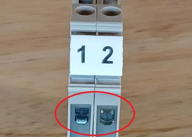
Figure 2. Close-up view of the lining of the screw-clamp cage.
The concept is very simple, but critics point to a key weakness: proper torque. Under-torquing the screw can lead to loosening and backing off under vibration. Over-torquing can twist the plastic housing and strip the screw, forcing replacement under a stressful time crunch. Proper torque is always listed on the manufacturer's datasheet, but can vary from less than 0.5 N-m (4.5 in-lb) to more than 30 N-m (22 ft-lb).
Figure 3. The action of a screw-type terminal block.
Tool-Operated Spring Tension
To solve the challenge of inconsistent torque that leads to wildcards in connection security, the next evolution of terminal blocks is a spring. The spring provides a constant force, pinching the wire between the spring and the metal cage wall. However, the pinching force of the spring must be temporarily released while the wire is inserted and removed.
There are two primary methods of relieving the spring force. The first method is using the screwdriver as a lever to directly open the connection point. Two disadvantages are that the terminal block requires more adjacent clearance for the screwdriver pivot, and it can warp the plastic with repeated use.
Figure 4. The action of a lever-activated spring terminal block.
The second method allows the cable end to simply press into the spring clamp, opening the mechanism. This type of block is termed “PUSH IN” in the Weidmuller catalog. Stiff wires can easily be inserted, so both ferruled and solid wires can be connected without a tool. For stranded wires, a screwdriver can press against a wedge, manually opening the mechanism to allow this more fragile wire insertion.
Figure 5. The action of a stranded wire in a PUSH-IN terminal block. Stiff wires don't requre the screwdriver.
Insertion Force
The spring provides the assurance of a constant clamp force, but the need for tools can be a limitation, especially when using stranded wires, which are common in panel construction. A more recent innovative method removes the tooling entirely when connecting the wires, replacing it with a trigger to provide the clamp at the right moment. This accelerates assembly, although a tool is still required for wire removal. This clamp method is termed by Weidmuller as “SNAP IN” because of the snapping sound that is heard when the trigger is activated.
Figure 6. The action of a SNAP-IN terminal block. Unmute to hear the 'click.'
Ferrules, or Free Ends?
Wire termination is a point of debate for terminal blocks. Although most blocks can accommodate solid, stranded, and ferruled wires, there are some benefits to using ferrule ends.
Go back and look at the videos again, and you may note that my wire samples were stranded. In some of the videos, you can see strands that have been forced out of the main bundle. If they are not clamped, the overall current capacity of the wire is reduced. If the strand somehow touches an adjacent terminal block, it can short out a branch circuit.
Ferrules provide assurance that all strands are connected to the terminal. The ridges from the ferrule crimp also provide a more secure surface for the clamp. However, it should be reiterated that terminal block manufacturers have designed the devices for solid, stranded, and terminated wires for many gauge and mm2 wire sizes.
More Than Just the Tools
This article has summarized the various activation methods for terminal blocks, but it leads to a second discussion. Terminal blocks are offered in a great many form factors and with extra accessories to accommodate special tasks. Check out the Part 2 article for a discussion about those terminal block types.
All images used courtesy of the author