Facebook
 Google
 GitHub
 Linkedin
What Does the UL508 Say About Wiring Connections?
Wire nuts? Soldering? Terminal blocks? Learn what the UL508 standard says about the acceptable types of wiring connections for industrial control panels.
Honestly, for someone who hates reading as much as I do, I’m shocked at the strange enjoyment I sometimes get when learning something new in the NEC or UL508 guide. Today, I was looking at a bus bar inside a VFD, and it made me wonder what the manual says about the various ways to connect wires.
Today, the information will be drawn purely from the UL508 manual. If you are working under the guidelines of a different jurisdiction, there may be crossover, but no guarantees. Also, this information is intended only to explain and define some terms; please do not use it as a replacement for reading and applying the rest of the standard to your own designs.
First, there is a distinction in the guide between power circuits and control circuits. However, while section 28 (2018 version) outlines the requirements for power circuit component connections, section 37 for control circuits simply refers us back to the power wiring section for compliance. For that reason, the topics described in this article are all derived from the power wiring section of the guide.
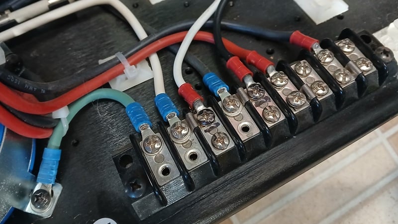
Figure 1. A set of wiring terminals on an open chassis power supply.
General Connection Requirements
Since every scenario is different, there are very few general requirements about how connections should be laid out. Much more is stated about the mechanism of mechanical interaction.
Here are the simple general requirements:
- Must be accessible for examination (and inherently for troubleshooting when needed)
- The wires must be able to be tightened or loosened without affecting the connection of any other wiring devices to the panel in general. Like don’t connect a ground wire to the lid hinge screw.
- All terminals should be rated for copper, aluminum, or both.
Types of Acceptable Connections
There is quite a long list of acceptable terminal connection types.
Pressure Wire Terminals
This category includes any connection where the bare wire is inserted and tightened by screw force. Examples of this kind of connection are bus bars in an electrical panel, screw-down terminal blocks, lever-action terminal connectors, and power distribution blocks with screw lugs.
Multiple connections into a single terminal are allowed as long as the connection is reliable and no strands of the wire were cut or moved out of the way so the wire could fit.
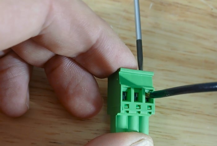
Figure 2. Clamping down a pressure wire terminal.
Quick-Connect Terminals
Two main connector types fit in this category. First, the type that are opened by the lever arm force of a thin, flat screwdriver and then the force is released to clamp down on the wire. Second, the new types of push-in connectors where the inserted wire presses on a trigger and activates a spring-loaded clamp.
Neither of these methods rely on the pinching action of a screw against a plate. However, they still must include some element of a dimpled or ridged plate so that the actual part that provides the clamping force isn’t just a flat plate against the wire.
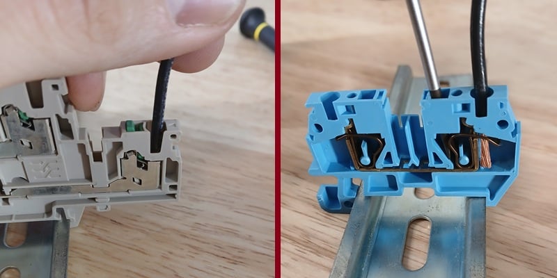
Figure 3. On the left, a terminal block that uses tool-free pressing force to activate (this one being a part of Weidmuller's SNAP IN series); just press and listen for the “click.” On the right, a traditional spring-clamp terminal.
Closed-Loop Eyelets
These connectors are similar in shape to the ring terminals used by automotive technicians, and they are quite common on grounding screws and multi-point distribution bars. The terminals may be crimped to the end of the wire, and when the end of the terminal is a closed eyelet, the screw is trapped. Unless the screw comes completely disconnected, the wire cannot slip off.
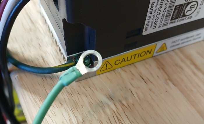
Figure 4. A closed eyelet terminal.
Soldered Connections
A soldered connection is more permanent, so it’s less likely to be encountered in panel assembly. But it is allowed under a few conditions. Before soldering, the wire must be wrapped at least halfway around a screw terminal, or have at least one right-angle bend if it’s passed through an opening, or, if it’s just a wire-to-wire connection, it must be wrapped around the other conductor.
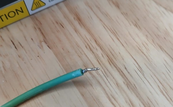
Figure 5. The soldered end of a copper wire.
Wire-Binding Screws
These wire-binding screws are the type you see on residential outlets and light switches. They are also common on earth-grounding screws inside motor drives and enclosures. The wires can be fitted with terminals that have eyelets, like the section above. They can also be used with soldered ends of stranded wire, as is common on grounding screws. They can also be used with solid wire, provided that it is wrapped at least ¾ of the way around the screw.
It is against the UL guide to simply bind down on the stripped, unterminated end of a stranded wire.
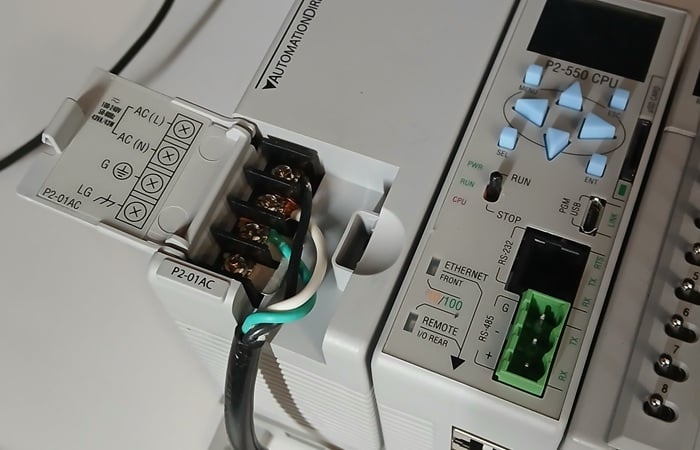
Figure 6. Unterminated ends of wires… Maybe I should practice what I preach, eh?
Open Eyelet
The closed-loop eyelets trap the screw and cannot come free easily. If the eyelet is open (like fork-end terminals), the wire can come loose if the screw vibrates just a fraction of a turn. These types of terminals can be accepted as long as they have upturned ends, or the ends somehow support and grip the screw shank so that it cannot disengage unless the screw physically comes out of the device.
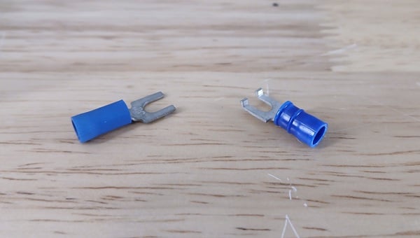
Figure 7. Open eyelets with and without upturned ends.
Ferrule Ends
Ferrules are incredibly helpful in reducing stray wire strands and managing multiple wires, but there are a few caveats (section 29.3.6). They can only be used with copper wire, and in terminals rated for copper wire. Also, ferrules are physical metal sleeves crimped around the wire, increasing its diameter. The guide states that, when the ferrule is installed, it must still allow proper electrical spacing between connectors.
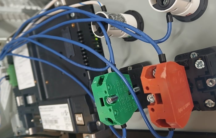
Figure 8. Ferrules attached to the ends of these panel I/O devices.
Bus Bars
Bus bar connections fit in the very first category, the pressure wire terminals. Due to the exposed nature of bus bars, there are a few insulation, material, and spacing requirements located throughout the manual to observe, as outlined in section 29.2.2.
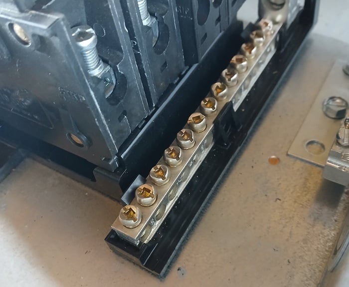
Figure 9. A bus bar as seen in a new residential power sub-panel.
Reliable Connections
The whole purpose of a listed standard for connectors is to ensure that wires stay connected and safe even under rough conditions. The guide can’t explain wire usage in every machine, since it’s all different, but keep these guidelines in mind, even if you are just building a small benchtop project. Required or not, these guidelines definitely lead to a safer, more secure machine assembly.
All images used courtesy of the author