Facebook
 Google
 GitHub
 Linkedin
The Difference Between 2 Wire RTDs, 3 Wire RTDs, and 4 Wire RTDs
We already discussed a few limitations of resistance temperature detectors (RTDs); this article will explore the difference between two-wire, three-wire, and four-wire RTDs.
Now that we've learned the basics of resistance temperature detectors (RTDs), let's delve into how two, three, and four-wire RTDs differ and how to choose the right one in the industrial industry.
2 Wire RTD Sensor
An RTD is simply a wire resistor, which, by its nature, only has two leads. Therefore, as the temperature increases, the resistance increases. A high-quality RTD typically uses a platinum wire, which has a linear, predictable resistance change with changing temperature.
However, if the platinum wire is attached to two copper wire leads, the resistance of the leads is significant. This introduces some limitations to the system, as longer leads mean more resistance, and the platinum wire makes up a smaller fraction of the total resistance.
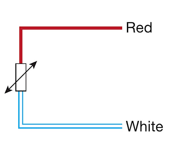
Figure 1. A simple color-coded two-wire RTD configuration. Image used courtesy of Thermometrics
A two-wire RTD system must be recalibrated when there is any sort of change to the system. For example, suppose a heat treatment oven is run at a higher temperature than its original design. In this case, the two-wire RTD must be recalibrated for the new temperature settings because the resistance changes in the RTD and in the lead wires. All of those resistance changes must be taken into account to produce accurate results.
Two-wire RTDs are generally not used in industry, but they help show some important concepts in resistance temperature measurements.
3 Wire RTD Sensor
To account for the lead wire resistance, one can use a three-wire RTD. Three-wire RTDs are the most common configurations in industry due to their accuracy and robustness. Additionally, they only require one additional wire.
A three-wire RTD has one lead attached to one terminal of the RTD and two leads attached to the other terminal of the RTD. All three wires are made from the same material, and are the same length, so that the resistances of all three wires are approximately equal.
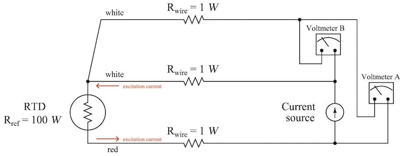
Figure 2. A typical three-wire RTD configuration. Sometimes, the two white wires in this image may have black insulation instead.
Figure 2 schematic shows three terminals, and two places voltage is measured. The voltage measurement at “Voltmeter A” represents the voltage drop across the RTD plus the voltage drop across the white wire leads, called “Voltmeter B.” Because each white wire has the same resistance (theoretically) as the resistance across the red wire, the voltage drop across the RTD is:
$$V_{RTD}=V_A-V_B$$
As the temperature changes, the lead resistance will also change, but when using the three-wire system, the resistance change will be predictable. This may be preferable to making a calibration table for each new environment the RTD will encounter.
Three-wire RTDs can be extended with approved cable extensions. These cable extensions have three identical wires and a standardized connector. This way, even though the resistance changes on each wire, it should change the resistance the same amount on each wire, and the voltage drop across the RTD will remain the same.
4 Wire RTD Sensor
The principles behind a four-wire RTD are the same as a three-wire RTD, except two wires are attached to each terminal of the RTD. This makes the four-wire RTD the most accurate, though the higher cost of using a four-wire RTD compared to a three-wire RTD may not be worth the extra cost, even for the improved accuracy.
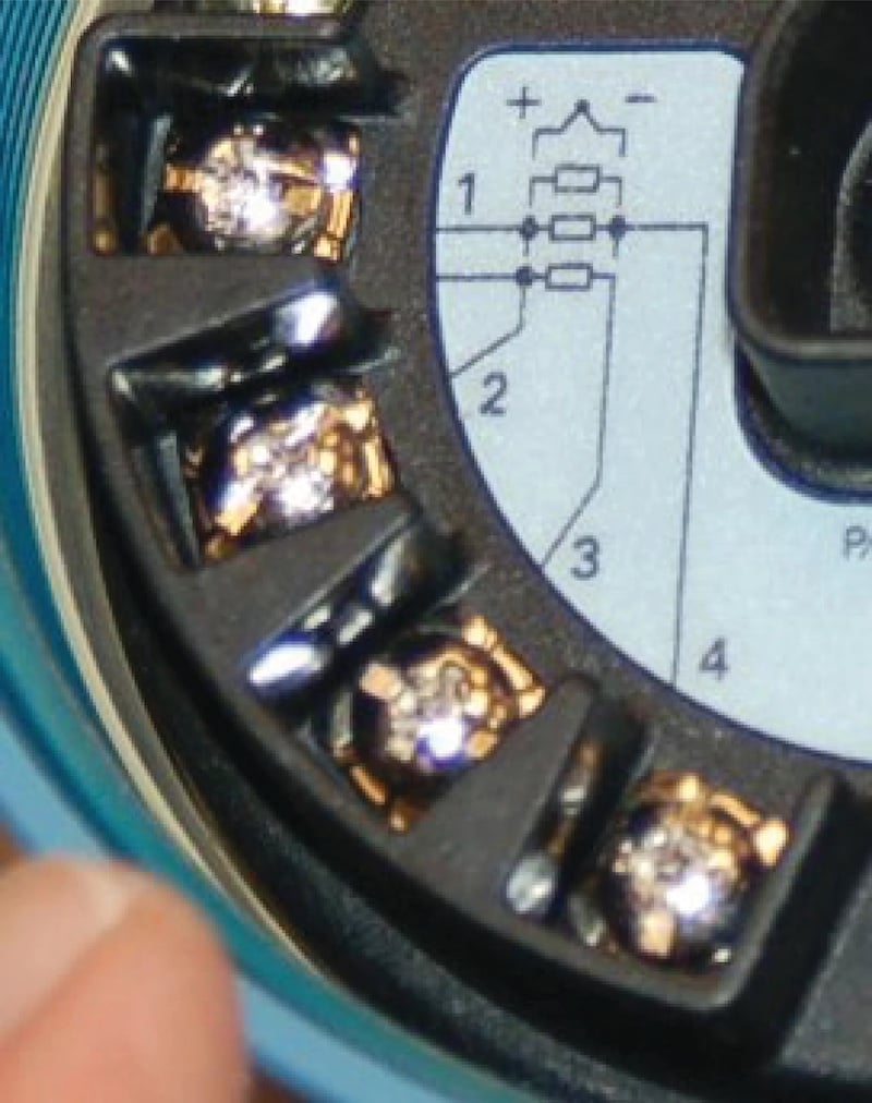
Figure 3. Temperature transmitter with up to four RTD terminals.
The advantage to a four-wire RTD is that it can be used in an environment where the wires are exceptionally long or may be exposed to a temperature gradient. This way, even if the wires are heated unevenly, each set of leads will have its resistance removed.
Choosing the Correct Resistance Temperature Detector (RTD)
Three-wire RTDs are often preferred to two-wire RTDs, and for good reason. Three-wire RTDs do not require a calibration table—like a two-wire RTD does. The wire length can be increased, within reason, provided all three wires are identical in material and construction.
For example, suppose an RTD was used in a control loop to change the flow of coolant to control the temperature of an exothermic chemical reaction. A two-wire RTD is used to measure the temperature, and with the use of a calibration table, it can perform well in this system. However, a new catalyst will drive the temperature a little higher, and engineering has decided the higher temperature is acceptable. Because the new temperature will increase the resistance of the wire leads from the RTD, a new calibration table is required.
Instead, suppose a three-wire RTD system was used. The new temperature requirement would mean an increase in lead resistance, just like in the two-wire system. However, because all three wires are (assumed to be) heated evenly, the lead-wire resistance is subtracted, and no calibration table is required. Thus, all of the resistance measured is due to the change in temperature of the RTD wire itself.
Much of the hardware for processing and displaying RTD data has up to four terminals with markings appropriate for each of the two, three, and four-wire configurations. Be sure that only the appropriate terminals are used. If the process calls for a three-wire RTD, do not run jumper terminals together. Remember that the measurements taken rely on all of the wires having the exact resistance, so a short wire will have lower resistance and lead to measurement error.
Likely, you won't use a two-wire RTD in the industry; however, three or four-wire RTDs may be used due to their increased accuracy. Which RTD do you use on the job, and what for?