Facebook
 Google
 GitHub
 Linkedin
Driving VFDs | What Does the S-Curve Parameter Mean?
Accelerating motors is a tricky topic, with profiles ranging from step inputs to polynomials. Which profile is the best choice, and why?
Digital control is cheap these days.
While VFDs may not be the choice for every motor starting application, it’s pretty common to use them in virtually every instance where an immediate start-up is less desirable than a ramp-up. Heavy loads and non-stationary objects will almost always benefit from ramping, and that’s what acceleration is all about.
Acceleration takes on a few forms, with the s-curve being the trickiest type to understand.
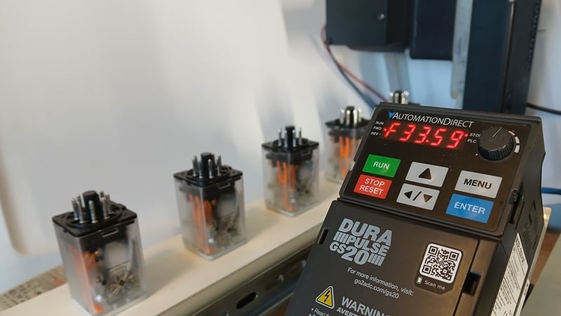
Figure 1. S-curve profiles are useful for heavy loads or objects that may shift under quick acceleration.
Types of Acceleration
There are three types of acceleration profiles in VFDs: step, fixed-ramp, and s-curve.
Step Input Startup
In this step input profile, the target frequency is reached immediately. The motor will catch up eventually, but because the rotor is stationary and not moving through the field windings, there is no inductive reactance, so the impedance (resistance) is lower while the driving voltage reaches its peak 60 times per second (for 60 Hz motors). This leads to a higher inrush current.
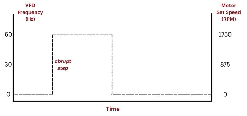
Figure 2. The step input.
For a visual, imagine driving a car and slamming the accelerator pedal to the floor to reach top speed almost immediately.
For a motor with a very light load, the target speed will be reached very quickly, and the consequence of the higher inrush current is minimized. Cycle times can likely be improved substantially when starts and stops are frequent.
Achieving a step input response is easy. Reduce the acceleration parameter to zero. This situation can likely get away with a more cost-effective motor contactor, but add in reversing ability, overload protection, and network control, and the VFD solution starts sounding very appealing.
Fixed-Rate Ramping
A ramp rate is so named because the motion profile (speed over time) looks like a ramp leading up to the target speed. Ramping is a first line of defense for reducing inrush current because the drive is not providing peak voltage to the coils nearly as rapidly at first. The output frequency starts at 0 and hopefully matches the rotor speed as it accelerates over time. A typical VFD will be able to ramp from anywhere between 0 seconds (a step input, no ramping at all) to several minutes. The time selection should be based on the loading and desire to balance cycle time with efficiency.
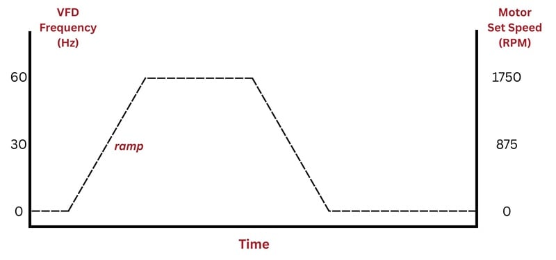
Figure 3. A typical ramp rate profile.
Why time units? Mathematically, acceleration is a unit of ft/sec2 or m/sec2. I’m not sure about you, but I have no idea what number to plug into this value for a reasonable effect. How much is 10 ft/sec2?
Instead, the VFD uses units of seconds. The value is literally the number of seconds it would take to accelerate from 0 to 60 Hz. If the motor is only accelerating a little bit, the time will be shorter but in the same ratio. Speeding up from 30 to 60 Hz? That will take half the time.
Ramp rates ease the initial inrush, but still cause an abrupt change in acceleration when the ramp starts, and then again when it reaches full speed. Use the car driving example again. A steady ramp rate is to suddenly press on the accelerator pedal, but not mash it to the floor. Hold it halfway down until you reach the top speed, then abruptly take your foot completely off the pedal.
To make the transition even more gentle, simply increase the ramp time. The downside of this is a longer cycle time.
S-Curve: the Gentler Alternative
Finally, the s-curve provides the smoothest transition between different acceleration points. The s-curve profile begins with the acceleration/ramp rate in its respective parameter, then adds a more gradual acceleration curve at the beginning, and ends with an equally gradual decrease in acceleration once the target speed is reached.
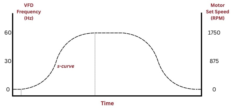
Figure 4. S-curve added to the accel and decel profiles.
This parameter is very helpful in situations where a load must be started gently, like a conveyor belt with round or top-heavy objects that might fall over with a sudden acceleration, even if it’s gentle. The VFD can start with a fairly small ramp time (faster acceleration) but add an s-curve to achieve that faster startup, yet still be gentle enough for fragile loads.
It’s important to know that the s-curve time will add to the given acceleration time. If you set the ramp parameter for 5 seconds and then add an s-curve, it will take longer than 5 seconds to reach the top speed.
In the driving analogy, s-curve represents putting your foot on the accelerator lightly at first, then pressing down harder to get up to speed. When you sense that you are getting close to the max speed, slowly take pressure off the accelerator.
Units of the S-Curve Parameter
Most VFDs follow one of two strategies for the s-curve parameter: either preset curves or a literal time input.
Preset S-Curve Profiles
Since the s-curve is more mathematically complex, it can often be simpler to provide the user with up to 10 different preset curve profiles which will be applied to the given ramp rate. The documentation must be consulted in order to determine the resulting total acceleration time (ramp+preset s-curve).
Time Input in %
This calculation relies on the ramp rate provided in another parameter. That ramp rate, multiplied by the %, provides an s-curve time. This time is an extension to the ramp time, which smooths the transition at the beginning and end of the acceleration.
With this strategy, as the ramp rate approaches 0 (a step input), the maximum s-curve is limited.
Time Input in Seconds
This calculation allows the user to explicitly state the amount of time added for smoothing the acceleration profile. In many cases, the user can choose the s-curve time for both the initial acceleration and reaching the target speed independently.
With this strategy, even with a small ramp rate, the s-curve may be longer. In many VFDs, the s-curve is automatically disabled if the ramp rate is set to 0 (step input).
All images used courtesy of the author
Related Content