Facebook
 Google
 GitHub
 Linkedin
Encoders vs. Resolvers: Applications and Characteristics
Learn the general characteristics of encoders and resolvers; these two components may seem to have much in common but are used in very different applications.
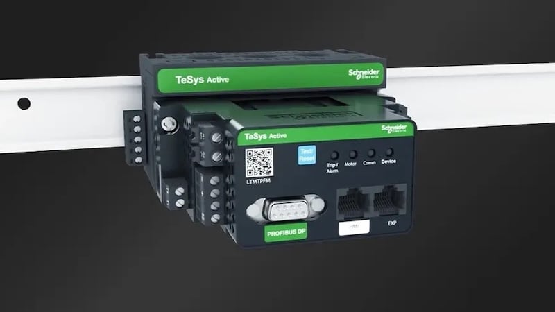
Resolvers and encoders identify the physical operating characteristics of equipment in operation. Generally, they measure the speed, the position of the shaft, and the direction of rotation. They are used in conjunction with AC and DC motors and provide real-time feedback of the machine in operation to the controllers using hardware connections. This feedback is used to adjust the power delivered to the motor to obtain the desired operating characteristics of the machine.

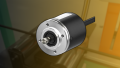
Figure 1. Resolvers and encoders are used to obtain operating characteristics of AC & DC motors.
Encoder Types and Characteristics
Encoders come in many varieties. According to the reading methods, encoders can be rotary or linear. According to the measured value, encoders can provide absolute or incremental values. On top of that, encoders can make use of sensing technologies like optical, inductive, capacitive, magnetic, or laser. Optical sensing is used in most cases, laser technology is employed in niche cases.

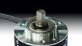
Figure 2. Diagram of a rotary encoder using an optical sensor. Image courtesy of Ryan VanOtterloo.
The image above represents a typical rotary encoder using optical sensors. The encoder shaft is coupled with the shaft of the motor to be sensed and is fitted with an interrupter disk which has evenly spaced cutouts along its periphery.
An LED light source emits a beam of light through the disk to the photodetector placed on the other side of the interrupter disk. When the disc rotates, light passes through the cutouts on the disk and is blocked in the areas where there are no cutouts. The photodetector measures light with a high or low voltage— a high voltage represents the time when the LED light hits the detector, and a low voltage represents the time the LED is interrupted by the disc. The digital output can be used to calculate the speed and angle of rotation from the starting position. The direction of rotation cannot be determined using a single interrupter disk.
Two-track interrupter disks can be used to determine the direction of the shaft. The disk will have two tracks: track A and track B. Each of the tracks have a respective LED light source and photodetector. Tracks A and B are offset from one other. This offset causes the signal measured by photodetector A and B to stagger.
According to whether the rising edge of track A or track B leads determines the direction of the shaft rotation. Disks with a greater number of tracks can be used for better resolution of the measured value. Having more tracks increases the accuracy and precision of the encoder. Having a higher number of tracks also enables absolute measurements rather than incremental measurements.
In addition to rotary encoders, the linear reading method can also be employed for encoders. A liner encoder makes use of unique patterns of cutouts present on a long, linear ribbon instead of interrupter disks. The number of cutouts passed per unit time gives the speed. There is no angular measurement in linear encoders, they are used in such applications.
The sequence of patterns observed in the signal can be used to ascertain the direction of movement. Laser sensors also can be used in an encoder. The laser beam is directed at a reflective surface on the moving part and the shift in the returning signal can help in the measurement of the operating characteristics of the machine. They are commonly employed in machines with horizontal or vertical moving parts rather than rotational movement.
Encoder Applications
Encoders are primarily used in speed and position control of AC induction motors and DC motors. They can be used in conjunction with AC and DC servo motors if commutation tracks are added to the setup. Encoders are used in most present-day industrial applications, including cranes, lifts, conveyor belts, moving parts of most robots, and more.
Currently, encoders are used more widely than resolvers. Encoders have higher accuracy and precision than resolvers. The implementation of encoders is faster and simpler. Also, they cost a fraction of the equivalent resolver. Due to electronic components present in encoders, it is not suitable for harsh environments with high temperatures and/or radiation. An advantage with the encoder is that, since the signals from the encoder are digital, they can be directly connected to a PLC without any controller or convertor in between.
Resolver Types and Characteristics
Resolvers are rotary transformers that provide analog output as cartesian coordinates of the angular position of the shaft. This information can be converted to speed, angle, and direction of rotation. The output of a resolver is two analog signals — one is proportional to the sine of the angle of rotation and the other is proportional to the cosine of the angle of rotation.
The speed can be obtained by the rate of change in any one of the signals with time. The direction of rotation can be found by knowing whether the sine or cosine signal leads. The three operating characteristics (speed, angle, and direction) of the machine can be obtained from the two signals of the transducer.
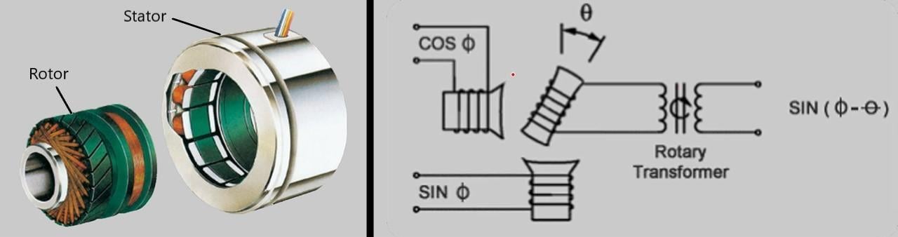
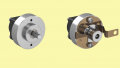
Figure 3. Representational image and circuit diagram of resolver. Image courtesy of Ryan VanOtterloo.
A resolver has two parts: a stator which is stationary and a rotor which rotates with the motor being controlled. The rotor and stator are not electrically connected and energy exchange between them happens via induction. The stator has two sets of windings — sine and cosine —which are positioned with a 90° separation.
The excitor located on the stator is energized with electric power at a certain frequency which induces a current in the rotor. When the rotor is coupled with the shaft of the motor to be measured, two signals are generated in the cosine and sine windings on the stator. These signals can be used to measure the operating characteristics of the motor.

Figure 4. The sine coil voltage moves along with the primary coil voltage and cosine coil voltage lags or leads by 90°. Image courtesy of Ryan VanOtterloo.
Resolver Applications
Resolvers are commonly used for speed control and motor commutation for permanent magnet (PM) motors and AC and DC servo motors. They are widely used in steel plants, paper mills, oil and gas production, jet engine fuel systems, and military transportation. Use in automotive applications (to know crankshaft position), aeronautics (position of flap) are some of the specific examples.
Since resolvers do not use any electronic components, they are suited for operation in harsh environments. Resolvers can withstand extreme temperatures, survive shock and vibration, and are even resistant to radiation. These help resolvers to be a substitute for encoders in rough environments where encoders are bound to fail. As resolvers give analog output, they need to be used with a converter to obtain a digital output.