Facebook
 Google
 GitHub
 Linkedin
How To Configure FANUC I/O: The Group and Digital Guide
Inputs and outputs play crucial roles in various automated processes. This article will explain the variances between digital and group I/O and offer guidance on setting up each type through Ethernet.
Many automated applications that utilize FANUC robots use input and output signals for communication and system control. The communication process is similar to how humans speak and listen. These signals provide information to the programmer about the system's status, such as the location of a part or the completion of a machining process, indicating that it is ready for unloading.
Configuration Assignments
Configuration is the first step to achieving communication to receive or send signals throughout the system. To begin configuring I/O, the programmer must know the rack assignment, slot location, and starting point.
The rack assignment depends on the communication type, such as Ethernet/IP, Profibus, etc. This informs the FANUC software on the communication type, creating the start of the gateway.
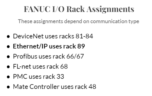
Figure 1. The values for assigning I/O rack numbers in a FANUC controller.
The slot location is the number that distinguishes individual I/O modules on a rack. It identifies the space on the rack where the particular module is connected. For example, if we wanted to connect a few field devices to the physical I/O headers in the cabinet (CRMA 58 and 59), this is slot 1 of rack 48, and would be referred to as "rack 48, slot 1."
Lastly, the starting point is the position on the I/O module that identifies the first port in a range that programmers can use. For example, if I wanted my range of digital outputs to be between 20-40, my range would be 20-40 with a start of 1.
If we wish to expand this example to Ethernet and communicate with some networked devices, we would configure rack 89, slot 1.
Even better, we can configure more than one I/O source at once, meaning that we can share data with networked devices, and attach a few local I/O devices at the same time.

Figure 2. Clarifying the rack assignment. This controller is meant to communicate through Ethernet/IP, so when assigning a rack, the value would be "89."
Digital I/O
Let's begin with digital I/O signals. Control signals (DI or DO) are sent to and from the controller. Digital signals are simple, as they can only have one of two possible states: ON or OFF. This simplicity makes accessing data for a single input or output signal line easy and makes understanding and managing these signals more manageable.
Digital I/O Configuration: Step by Step
Configuring digital I/O is a straightforward process. The first step is navigating to the FANUC teach pendant's digital input or output screen. This can be achieved by pressing menu > highlight “I/O,” and cursor over and down to Digital, then press enter.
This will take you to the digital input or output page. Switching between inputs and outputs is as easy as pressing the IN/OUT tab at the bottom of the page.
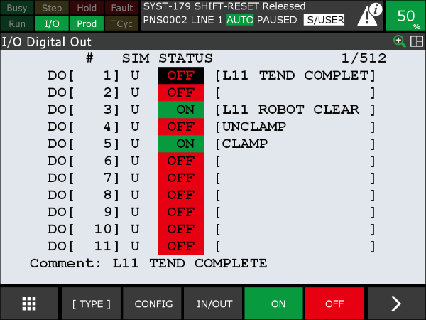
Figure 3. The digital output page of FANUC's teach pendant.
To configure these signals for communication protocols, press CONFIG on the bottom of the screen.
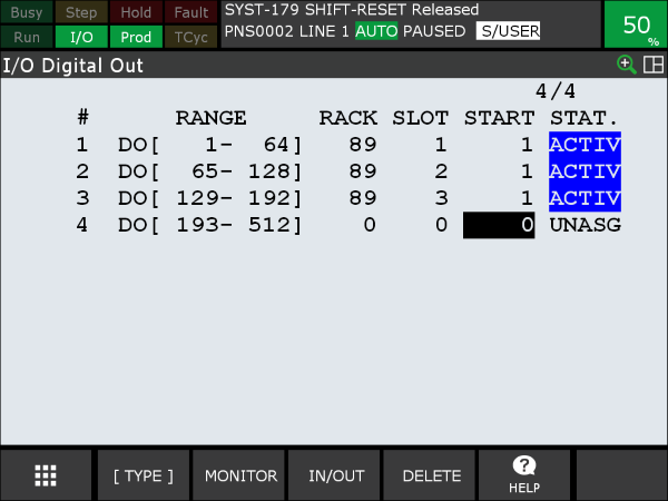
Figure 4. The configuration page for digital outputs.
This page determines how the signals communicate. The range, rack, slot, and start must be entered based on the personal configurations the user is trying to achieve.
In the above image, the range for line one is set to 1-64 in slot one, starting from one. This configuration allows the first 64 digital output signals to be used. If the start were 2, the first digital output signal would not be within the communication gateway. In this example, the communication protocol used is Ethernet/IP, so the rack is set to 89.
Connections to different Ethernet networks can be assigned to the next slots, but a single configured adapter configuration will be slot 1.
Once digital input or output signals are configured, the assignments must be verified by pressing F2 on the teach pendant. A correct assignment will show “port assignment is valid,” while an incorrect assignment will show “port assignment is invalid.” The user must cycle power to enable (activate) the changes once a valid signal is displayed on the teach pendant.
Group I/O
Group I/O signals (GI or GO) consist of small ‘bundles’ of digital I/O signals interpreted as binary integers. A group signal comprises a sequence of 16 ones (1) and zeros (0), representing the ON or OFF states. Each group input or output bit corresponds to a single digital input or output line. Any unused bits are assigned a value of "0".
Grouping digital I/O enables programmers to manage or monitor the sequence of I/O signals within a program by setting or reading a single group.
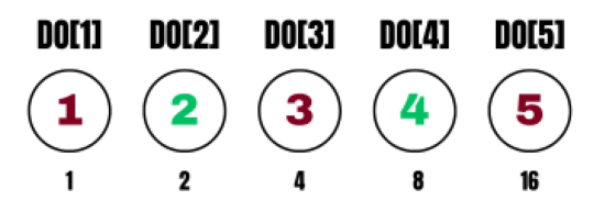
Figure 5. In this example group output, we see that only digital outputs 2 and 4 are ON, resulting in a binary integer value of 10 when the signals are in the desired position.
Group I/O Configuration: Step by Step
Users must first navigate to the group I/O page on the FANUC teach pendant to configure group inputs or outputs. To do so, press menu >, highlight “I/O,” move to the Group tab, and press ENTER.

Figure 6. Menu for group outputs on the FANUC teach pendant.
Configuring group I/O is very similar to digital I/O, except that we must determine how many digital points are to be included in the groups.
To configure the group outputs or inputs, press F2, CONFIG. Then, determine the digital I/O signals intended for grouping. Remember that when you define a group input or output, it must contain between 2-16 signals; these signals must all use the same communication protocol (rack), and must be in the same slot.
Figure 7. This is the group output configuration page on the FANUC teach pendant.
We can receive group inputs from Ethernet, perhaps to receive positional target values, in which case we can use rack 89, slot 1. Or, perhaps we have an array of sensors to determine the size of a pallet, so we could use rack 48, slot 1.
After determining the signal source, enter the start point and the number of points from the digital I/O page. For example, if we wanted a 5-bit GO starting with DO[22], the start point would be 22 and the number of points would be 5. Now, points 22-26 would be grouped. If you are already using digital I/O for other signals, do not use those same points in the new group I/O.
Press "NEXT" and verify that the assignments are correct. Finally, cycle power to enable the changes.
Understanding FANUC Group and Digital I/O
Understanding how to configure FANUC I/O, including digital and group I/O, is essential for effectively programming and managing automated processes. Following the step-by-step guidance given in this article, programmers can successfully set up and configure digital and group I/O signals through Ethernet, enabling communication and system control.
All article images used courtesy of the author; featured image used courtesy of Adobe Stock