Facebook
 Google
 GitHub
 Linkedin
How to Troubleshoot Resolvers
Learn about the electrical characteristics of resolvers and how to properly conduct different troubleshooting tests to ensure they run at their highest performance.
Resolvers are electromagnetic sensors that provide analog output to measure the degrees of rotation on the motor to which the resolver is attached. They consist of two sets of windings: primary and secondary.
The primary winding is placed on the rotor and moves along with the load in the excitor. The two coils in the secondary windings are kept at 90°, offset to each other. Encoders have replaced resolvers in most aspects of commercial use. However, resolvers are still presently used in harsh environments where the components have to withstand extreme temperatures or radiation.
Resolver’s Key Electrical Characteristics
In order to properly troubleshoot a resolver, it's important to know its key electrical attributes. These include:
- Input excitation voltage: The input AC voltage and frequency applied at the primary windings. The voltages range from 1 to 26 VAC and the frequency can be in the 400 Hz to 1000 Hz range.
- Transformation ratio: The ratio of the output voltage to the input voltage of the resolver. A resolver is essentially a rotary transformer — the winding design determines the transformation ratio. In most cases, the voltage is stepped down in a resolver.
- Maximum input current: The maximum permissible current to be applied to energize the primary windings. Current is a function of voltage and resistance (I=V/r). The manufacturer specifies the maximum permissible input current.
- Output voltage: The output voltage from the secondary coils of the resolver.
Testing the Installation of a Resolver
While designing or implementing a new resolver, it is useful to identify the operational limits of the component. These simulated tests can be done in an enclosed test environment to minimize any potential downsides while conducting the tests. The excitor of the resolver is connected to a signal (waveform) generator. The output from the sine coil and the cosine coil can be observed through a dual-channel oscilloscope.

Figure 1. Signal generators can be used to test the limits of a resolver.
Known errors are added to the input signal to check whether the resolver can withstand them. If the resolver fails, the design needs to be altered or another resolver with suitable specifications needs to be used. In addition to adding errors, the frequency/amplitude/waveform shapes can be altered to observe when the system fails.
The output waveforms should be verified if they meet the specifications of the resolver being tested. The sine coil output has to be leading or lagging the cosine coil output according to the direction of operation.
Since resolvers produce an analog output, they are almost always used with a resolver interface card. The interface card accomplishes two functions for the resolver: it supplies the necessary power required to drive the resolver and receives and analyzes the output signal of the resolver. Since these cards are electrical components, they should be separated from harsh operating conditions such as extreme temperatures, voltages, and radiation levels.
A resolver has to be selected according to the maximum power capabilities and other parameters of the resolver interface card. The software controls that can be used depend on the interface card and the larger SCADA in which the installation is part of.
Potential cabling losses have to be considered while installing resolver. Cabling losses can cause disturbances in the output voltage measured. This can occur when the resolver interface card is separated from the harsh environment in which the resolver operates. A low-capacitance, shielded, twisted-pair cable can be used in such a scenario to avoid cabling losses.
Troubleshooting Resolvers
Typically, the cables of a resolver are color-coded for easy identification: white for the excitation coils, yellow and blue for the sine cables, and red and black for the cosine cables. It may vary according to the manufacturer. Consulting the manual for the particular device is advised for more clarity.
Resistance Measurements
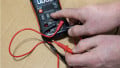
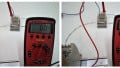
The simplest test that needs to be conducted to eliminate resolver damage can be done using a multimeter. Set the multimeter to measure resistance in ohms and measure the resistance across each of the three coils:
- Across the white cable to measure the resistance of primary windings
- Across yellow and blue cables to measure the resistance of sine coil windings
- Across red and black cables to measure the resistance of cosine windings
The sine and cosine coils should be showing identical resistance values. The resistance value for the excitation coil will be different. If any of the coils show a reading of infinity, the resolver is damaged and needs to be replaced. The readings can be checked against the manufacturer's specifications to identify if there is any shift from the factory specifications.
Input Voltage
If the resolver seems to show the correct resistance measurements according to the specifications, check the input voltage supplied to the resolver. If the input voltage is low, the output detected will be small since a resolver is essentially a stepdown transformer. IF the input voltage is low, the problem lies with the resolver interface card. The solution to that will depend on the interface card. If the power output of the interface card can be adjusted, match it with the input requirements of the resolver. If there is no option to adjust the voltage, the interface card needs to be replaced.
Cabling Loss
A common problem that occurs in a resolver is with the output voltage. If there is no voltage drop at the output cables of the resolver but there is a drop at the resolver interface card where the readings are taken, it is due to cabling losses. This loss is common when the resolver interface card is installed away from the resolver to separate it from the harsh working conditions. Use low capacitance, shielded, twisted-pair cables to avoid cabling losses.
Axial and Radial Offsets
To check axial and radial offsets, a dual-channel oscilloscope is required. In addition to that, a signal generator can be useful while troubleshooting. The output cables of the resolver are connected to the oscilloscope. If the oscilloscope is capable of three traces, the input voltage also can be traced to the scope. If there is a change in the output voltage, electrical errors, or a phase shift, it could be due to axial or radial shifts. These shifts may occur due to the improper installation of resolver, to a buildup of system tolerances, or defective hardware.
A decreased output voltage, a slight increase in electric error, increased phase shift, and increased input power and current indicate axial offset. A proportional increase in electric error, a minimal phase shift, a minimal change in output voltage, or a small reduction in input current and power indicate a radial shift. According to the symptoms displayed, the resolver can be manually reset or needs to be replaced.
A problem can occur in a resolver for more than one reason. While troubleshooting, the complete battery of inspections needs to be conducted even if one problem is identified.