Facebook
 Google
 GitHub
 Linkedin
An Introduction to Types of Closed-loop Motor Control
Closed-loop motor control is a control system used to regulate the output of a motor. Learn about the four common types of closed-loop motor control systems to understand each one’s inner-workings and applications.
A control system in which the output has an impact on the later input to the process is known as a closed-loop control system. The output is compared to the desired benchmark—if it diverges from that benchmark, the input automatically adjusts to attain the desired output. In simple words, the input is adjusted by taking feedback from the output.

Figure 1. Schematic of closed-loop control system
An air conditioner is an excellent example of a closed-loop control system we encounter every day. The user sets the desired temperature and the air conditioner starts working. While on, the AC unit checks the temperature of the room. If the room is warmer than the set temperature, it keeps running. When the desired temperature is reached, it stops. It is a very simple closed-loop control system. The AC unit controls the room temperature and determines whether to keep running or stop.
Closed-loop control systems also extend to motor control. In this article, we explore the different types of closed-loop motor control systems to understand each one’s inner-workings and applications.
Closed-loop Motor Control
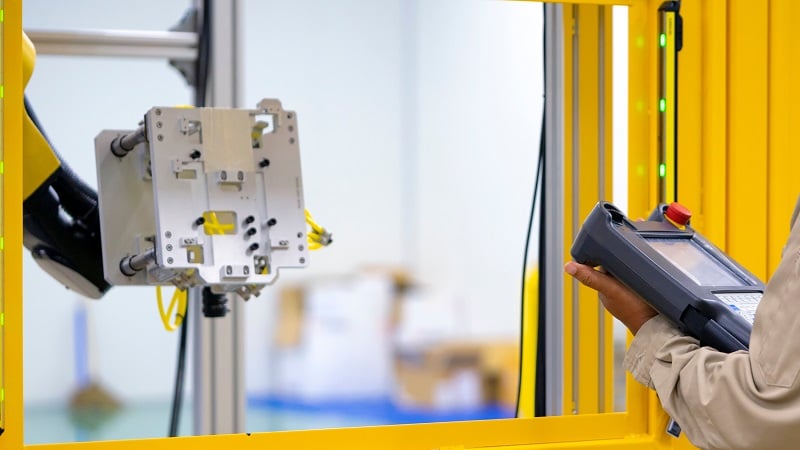
In industrial applications, it is desirable to control the output of a motor. Closed-loop control of a motor offers superior control with minimal need for human intervention.

Figure 2. Closed-loop motor control regulates the inner-workings of a motor.
Closed-loop motor control is a control system used to regulate the output of a motor. A sensor constantly measures the output characteristics of the motor and the sensor output acts as feedback to regulate the input. The sensor could be a tachometer, optical encoder, Hall-effect type positional, or rotary sensor. It depends on the type of motor to be regulated.

Figure 3. Schematic of closed-loop motor control
Closed-loop motor control is one of the most common way to regulate the output speed of the motor’s varying load conditions. When there is a change in the load condition, the speed of the motor changes, and the feedback is fed to the potentiometer at the input setpoint. This loop continues until the desired speed is reached. Closed-loop motor control can also be used to control torque, improve steady-state accuracy, and provide protection to the motor.
Types of Closed-loop Control Systems
The general schematic of closed-loop motor control is shown above in Figure 3. The main parts of the system are a controller, current limiter, sensor, and convertor. The converter converts variable frequency to fixed frequency and fixed frequency to variable frequency. As the name suggests, the current limiter does not allow current to increase beyond a set value. This article looks are four types of closed-loop motor control.
Current Limit Control
Current limit control is used to limit the current to the converter and motor for quick variable operations. The feedback in this is the motor current and is fed to a threshold logic circuit.

Figure 4. Schematic for current limit control
The threshold logic circuit only monitors until the motor current is below the maximum permissible current. Once that is breached, the feedback loop activates and forces the current to normal, and, once it has been achieved, the feedback loop becomes inactive.
Closed-loop Torque Control
Closed-loop torque control is most common in electric automobiles and locomotives. The desired torque for the motor is determined by the accelerator as reference torque (T*) in Figure 5 below.
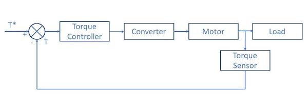
Figure 5. Schematic for closed-loop torque control
The output of the motor is measured using a torque sensor. If the measured torque is less than the desired torque, the torque controller pushes to provide more torque. It goes on until it reaches the desired torque. In electric cars and automobiles, this takes just split seconds. The feedback loop is activated multiple times in a small timeframe.
Closed-loop Speed Control
A closed-loop speed control system has multiple feedback loops for motor control. The inner loop is a simple current limit closed control loop. The inner loop also keeps the torque output below a safe limit. The outer loop helps to control the speed of the motor. The schematic for closed-loop speed control is given below.

Figure 6. Schematic for closed-loop speed control
The reference speed of the system is ω*m, and the actual speed of the motor, measured by the speed sensor, is ωm. This produces a positive error of Δ ω*m. This speed error passes through the speed controller and current limiter. For even small errors, the current limiter is overloaded and sets the reference current for the inner closed control loop. This accelerates the motor and the motor speed increases. This decreases the speed error Δ ω*m.
Once the motor speed equals the reference speed and later accumulates a negative speed error, the current limiter saturates and starts to act as brakes to the motor. This is how a simple, closed-loop speed control works.
Closed-loop Speed Control of Multi-motor Drives
Such control systems are used when multiple drives share the load. When different motors work in synchronization to share the same load, the speed and torque should be controlled to avoid the imbalance in the load shared between the motors. Even if the different driving motors have different ratings, they should be running at the same speed.

Figure 7. Schematic for closed-loop speed control of multi-motor drives
If the individual driving motors generate their torque requirement, the driving shaft needs only synchronization torque—a small requirement. On the other hand, if one of the motors does not generate the necessary torque, the driving shaft needs to carry the deficient torque in addition to the synchronization torque required. These are just some of the many challenges the closed-loop speed control system has to overcome while driving multiple motors simultaneously.