Facebook
 Google
 GitHub
 Linkedin
Safe and Connected | An Intro to IO-Link Safety
IO-Link technology keeps improving, and with the recent introduction of Safe IO-Link, the automation world is going to get a whole lot more modular.
When machine builders are designing equipment that might make your smartphones, tablets, or even valve cartridges, the safety of the operator is paramount. Safety devices are tested thoroughly and designed to fail in a safe position.
Safety In Automation
Devices designated for safety need to communicate with a similarly safety-dedicated control system, which might be hard-wired signals to a safety relay, or it could be commands over a safe Ethernet protocol such as ProfiSafe or CIP Safety.
Recently, the industry has seen a trend to digitize signals (all channels over a single wire, rather than a discrete/analog wire for each device). This saves time and money when wiring field devices. A new safety communication protocol has emerged on the market recently called IO-Link Safety, which uses IO-Link technology and topology but supports safety devices to connect directly to a safe IO-Link master.
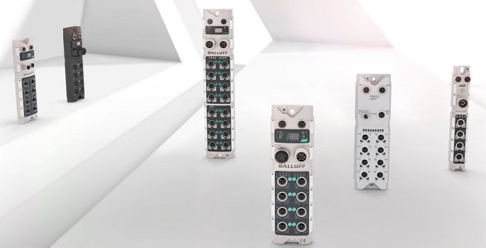
Figure 1. A collection of Balluff IO-Link masters. Image courtesy of Balluff
What Is IO-Link, Anyway?
The IO-Link topology consists of a master device, optional signal distribution, and one or more end devices. The end devices can be flow meters, I/O blocks, analog sensors, motor drivers, or even other IO-Link masters, just to name a few. The devices plug into the master with standard M12 cables, and the master offers a bridge to communicate to a control system using a field bus of your choosing. Standard field buses are supported, such as PROFINET, Ethernet/IP, Modbus, and EtherCAT. Some PLC manufacturers are even offering standard IO-Link ports or modules integrated into the controller.
Each device that plugs into the master contains real-time monitoring, configurable parameters, and diagnostics, in addition to the normal I/O data. This data is accessible over the fieldbus protocol and is mapped into different registers (tags) in the PLC. This makes even a simple sensor able to be configured remotely without the need for dip switches or special wiring.
The wiring of an IO-Link system is always the same, which makes the design and manufacturing of IO-Link devices simple. The data is sent over a two-wire digital communication so that the signal is not susceptible to electronic noise.
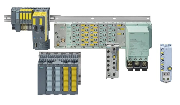
Figure 2. The ET200 distributed I/O system with safety I/O. Image courtesy of Siemens
Why are Safety Protocols so Important?
When equipment has moving components, the operator needs to be protected. A simple fence around the equipment will often suffice in protecting operators. If you need to gain entry past the safety fence, a door will need to be installed, and you will need to monitor the position of the door in the fence. This is where safety devices come in.
A safety device protects operators by monitoring and stopping the tooling if the safety conditions are not met. A safety gate interlock will have a mechanical or magnetic way of detecting that the door is closed. An E-stop button allows signals to pass through the contacts if it is not pressed, but once pressed, the signal will break and the equipment will stop.
Because these devices are all ‘safety’ rated, they will need to have dual redundant circuitry, which is used to verify that the status is correct. If this circuitry fails, the status will not be true, and the equipment must stop.
Sending Signals ‘Over’ a Protocol
Sending statistics and signals over a fieldbus protocol is common practice in automation, but these protocols do not care about the amount of time it takes for a signal or command to reach its destination. If a network is overloaded with traffic, the time it takes for a round-trip command will be very long, and this functionally will not work for a safety system.
If a safety light curtain beam is broken, the system needs to react immediately. To allow safety systems to communicate over an industrial protocol, there needs to be a time stamp associated with each message. The network itself also needs to be robust and include fail-safe protocols. These features are not included with standard industrial communication protocols.

Figure 3. A Safe IO-Link master from IFM. Image courtesy of ifm
IO-Link Safety Technology
Today, we already have CIP safety, ProfiSafe, and FSoE protocols, which have the requirements to send inherently safe signals over the Ethernet infrastructure right along their non-safe counterparts. Servo drives have been using this technology for quite some time.
The IO-Link Safety protocol is built on the IO-Link standard that uses non-safe devices, but supports smart safety devices such as safety IO blocks, light curtains, and other safety-rated components, and communicates with the control system over one of the safety protocols.
One IO-Link master is capable of connecting and controlling non-safe and safe IO-Link devices over the same safe field bus protocol. By using a safe IO-Link master, machine designers can create stand-alone cells with field I/O and safety I/O from one power cable and one Ethernet cable.
The Advantage Of IO-Link Safety
Typical safety systems, such as a light curtain, require wiring from the device back to a safety input in either a panel or a remote I/O rack. If you have multiple light curtains, they all need to have their own cables routed back to the electrical panel. This results in miles of cable runs.
Wiring the safety input channels offers another set of challenges. Safety inputs typically have test pulse channels that need to be wired correctly; if they are not, the system will fault. By using Safe IO-Link technology, these problems go away. Simply plug the light curtain into the IO-Link master, and the programmer can configure, diagnose, and monitor the status of the curtain.
If you determine during integration that you need additional safety outputs, simply plug in a safe output block into the IO-Link master, and you will have multiple safety-rated outputs in the field.
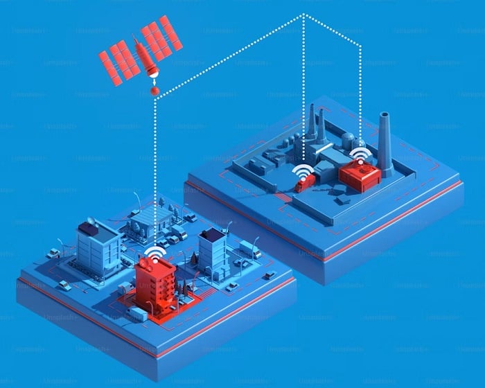
Figure 4. A graphical concept of modular automation. Image courtesy of Unsplash
Flexible Machine Building
Manufacturers are requesting machines faster today than ever before, and because of this high demand, machine builders need to have flexible machine designs that can be modified to the customer's requirements quickly and efficiently.
By using technology like safe IO-Link, machine builders can adapt their standard designs to fit the requirements of the customer, therefore satisfying the need for equipment designs to be flexible.
Featured image (modified) used courtesy of Pilz