Facebook
 Google
 GitHub
 Linkedin
Commissioning IO-Link Part 1: System Configuration
IO-Link devices can be inputs or outputs, and often a mix of both. In this article, learn how to interpret datasheets that list the indexes and purpose of the bytes to read and write process data.
During the past few weeks, I’ve been studying IO-Link network connections to better understand how to quickly adapt input and output devices, which is the touted strength of this innovative protocol.
There are a number of important lessons learned, including the various ways to configure the I/O devices (but not all of them can use the data for process control logic), the structure of the bytes and associated bits to read input and control outputs, and finally, a few networking principles that apply to entire networks, not only to IO-Link devices.
In this article, we’ll discuss the process of configuration and what sorts of parameters are adjustable before running the system.
First, we should define what is included in an IO-Link network to understand what we’re dealing with. The I/O devices themselves are proximity sensors, position switches, flow and pressure sensors, and even output devices like stack lights and valve interfaces. Some other common devices include IO-Link just for monitoring, like power supply modules.

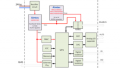
Figure 1. This set of IO-Link devices includes, from left to right, a network cable, an IO-Link master, a 3-tier stack light, two sensors, a hub, and an I/O cable. Image used courtesy of the author
These IO-Link devices all attach back to an IO-Link master via M12 cables. The master is a fieldbus hub that collects and distributes the data from the I/O devices and communicates with the controller. To further expand a network, hubs and splitters can multiply the number of available IO-Link ports.
Major IO-Link manufacturers include SICK, Balluff, ifm, Keyence, Pepperl+Fuchs, Banner Engineering, Endress+Hauser, Turck, wenglor, and many others. It’s an increasingly common industrial standard protocol.
Configuring an IO-Link Master
Configuring is just a fancy word that means setting up a device so that it’s ready to share data with the controller. For the I/O devices themselves, it usually means teaching one or more trigger set points, choosing a high or low output when the sensor is energized, or, for output devices, setting the brightness or color of a stack light element and other items.
For an IO-Link master, configuration usually deals with determining each port as a standard or IO-Link format, and if it’s standard, toggling between input and output. Not all IO-Link masters support this dual functionality, and sometimes only half the ports may toggle between standard and IO-Link format.
One important note for those ports in the standard I/O format: two of the four M12 pins are dedicated to the power supply for the device, leaving two more pins that may receive inputs from two sensors or send controls to two outputs. In this way, an IO-Link Master with 8 ports may actually control up to 16 I/O devices, provided they are not set up for IO-Link.
Configuring Through a Web Server
Most Ethernet master devices have a default or custom IP address that can be typed right into the computer web browser to access some amount of data from the modules and the attached devices, but they cannot be controlled with logic. You may be able to see a live view of the port I/O status and error messages. You can also access and edit some device properties. A specific example in my case, using a modular stack light, I can adjust the default brightness of the LEDs from the web server.

Figure 2. Web server configuration for the network settings of the IO-Link master. Image used courtesy of the author
Another note about web servers is that they can be accessed while the device is connected to the controller but be warned: online changes can and likely will affect the live manufacturing process.
Configuring Through the Controller
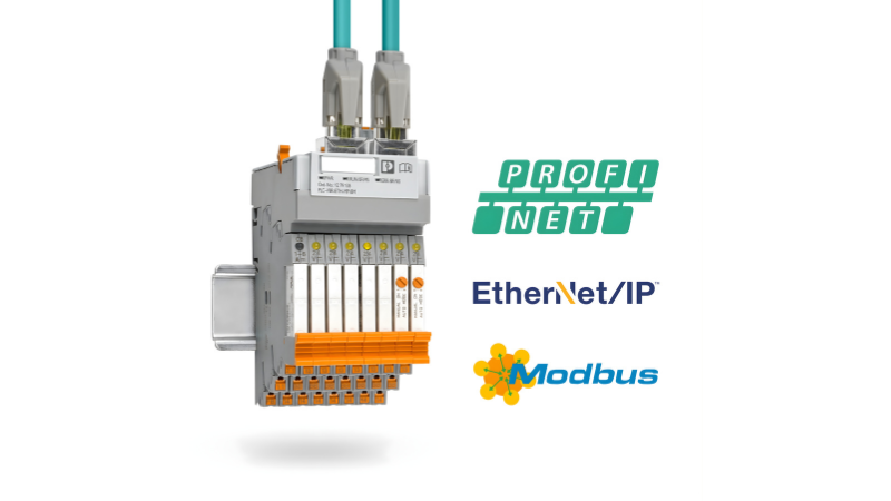
When the IO-Link master is added to the controller, it may be through the installation of an electronic datasheet (EDS) or the creation of a generic Ethernet module. For EtherCAT, the alternative to an EDS is an EtherCAT Subdevice Information file (ESI), and for PROFINET, the file is called a General Station Description (GSD). The appropriate file must be added to identify the number and integer size of input, output, and configuration words.
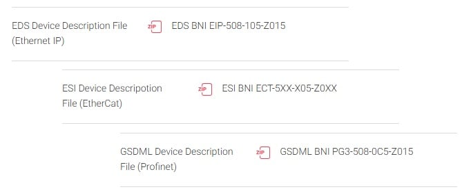
Figure 3. The file downloads for three different types of IO-Link masters, one product for each network. Image (modified) used courtesy of Balluff
How to translate and actually use those command words varies by IO-Link master, and at an even deeper level, it varies by the actual I/O device that’s connected to each port, and we’ll cover some examples of these process data variables in a separate article.
Configuring Through Dedicated Software
Some IO-Link master and gateway devices include a serial connection port (or USB) that connects directly to a PC to handle tasks that a PLC cannot. Take a sensor, for example. The PLC can read the high/low status from the sensor, but it cannot teach the set point thresholds. Dedicated software is used to set the trigger points. Depending on the device, some sensors can include timing, logic, multiple set points, and others.
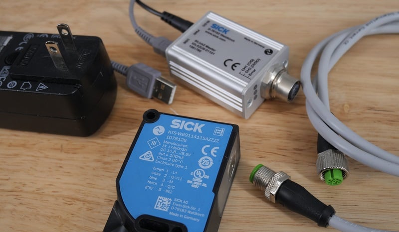
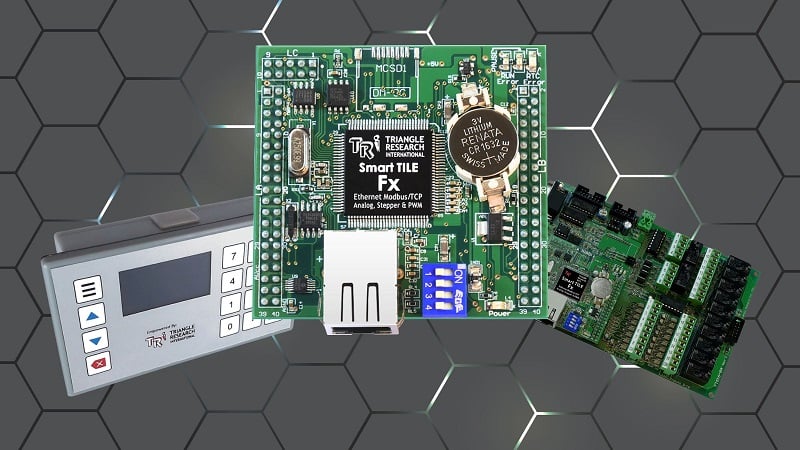
Figure 4. SICK IO-Link devices can be individually configured with the USB tool and the SOPAS software. Image used courtesy of the author
The proprietary software can configure the I/O devices and other hubs/gateways. Some examples are SOPAS from SICK, Balluff Engineering Tool, the Banner Sensor GUI, and others.
Author's note: It is possible that some sensors may be able to be remotely taught over IO-Link directly from the PLC, but I'm not aware of any.
Configuring the IO-Link Master
IO-Link can be a tricky protocol to get started. Configuration is only the first step, and after this, we actually need to understand what bits to read or assign. When the master is added to the PLC, the tag listing contains hundreds of bytes that must be read or written into. In the next article, we will use the manufacturer’s datasheets to understand what these bytes mean and how to use them.