Facebook
 Google
 GitHub
 Linkedin
Simple Connection: Driving Standard I/O With IO-Link
Sometimes switching to a new network protocol means updating all of the devices to this new standard, just so they all communicate. Fortunately, IO-Link includes simple connections baked right in.
I’ve been working with IO-Link quite a bit recently, thanks to some generous product contributions from Balluff, a leading manufacturer of industrial field devices. Every IO-Link manufacturer puts an individual twist on IO-Link, usually in the form of configuration software, but there are many similarities.
Perhaps the most significant of those similar factors is the flexibility that allows IO-Link to combine advanced diagnostic, data-rich I/O with traditional field devices. You see, IO-Link is a protocol, and the thought of adding a new protocol to any system can be intimidating. Are we talking about a full changeover from one protocol to another, or even just the field devices? That sounds really difficult, expensive, and risky, so more than likely, we’d refuse unless there was a really good reason.
Pairing IO-Link With Standard I/O
IO-Link mainly comes in two categories, with a less-common third one. The two main categories are IO-Link masters and IO-Link field devices.
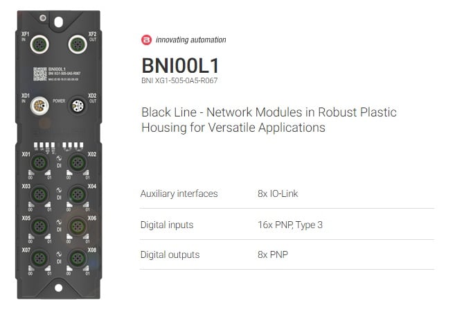
Figure 1. An example of an IO-Link master with configurable I/O: it can be IO-Link or standard I/O.
The IO-Link masters are the central communication hub that converts the field signals into a common industrial protocol. They are usually designed as machine-mounted units with M12 connectors for data and power. Sometimes the masters are modules that fit onto the PLC rack, and do not have the rugged machine-mounted form factor. Regardless of which type, they have multiple ports that accommodate the IO-Link devices.
These devices are the sensors, indicators, and even motor drives that actually interface with the people and the process. They are usually a lot more capable than traditional similar devices. Sensors may have an analog output, multiple configurable trip limits, diagnostic and alarm data, internal temperature signals, measurement quality value, and more. A common indicator is the IO-Link stack light with many operating modes, custom color configurations, and more.
As you could guess, it may be overkill for simple situations, and certainly more expensive than PNP/NPN discrete sensors. Indeed, for most situations where IO-Link is needed, we probably want to continue using a few of the good old-fashioned I/O devices.
Individually Configurable Ports
On all IO-Link masters that I have seen (I could be wrong, but I couldn’t find any), most of the I/O ports can be switched between IO-Link and standard I/O. You can freely choose whether the port is dedicated to an IO-Link device, or whether it can be a discrete I/O signal.
Even more interesting is this: most of the ports can be toggled to have 2x standard individual I/O signals, so if you have an 8-port master, it may handle up to 16 standard I/O signals. These can handle sensors or small outputs. Different classes of IO-Link ports support different output currents, so we do need to keep an eye on power-hungry I/O devices.
Those standard I/O ports are set up to deliver 2x signals per port, usually on pins 2 and 4. For electricians, that means the black and white wires of the M12 cable.
Cautions
These models may differ in two key ways: the number and polarity of these configurable I/O ports.
Number: Some IO-Link masters allow an open configuration of all the IO-Link ports. Others may only allow half of the ports to be configured. The quick way to verify (if it’s not spelled out right on the datasheet) is to check the number of “standard” I/O ports. If the data lists 8x IO-Link ports and 8x standard I/O, then we can safely assume that only four of the ports can be switched, each providing two I/O signals.
Polarity: When I/O enters the conversation, obviously, the technician needs to consider the NPN/PNP question. Check the datasheet to be sure that you’re purchasing the right part. However, beyond the NPN/PNP question, there is the matter of input vs. output. Each of those ports can handle two I/O signals, and while you might find that they can both be inputs, only one may be capable of driving an output device.
The way to verify is, once again, handed to us on the IO-Link master datasheet: if it lists 16x PNP inputs, but only 8x PNP outputs, then we know that all 8 of the ports can be switched to standard I/O, but only one pin can be used as an output.
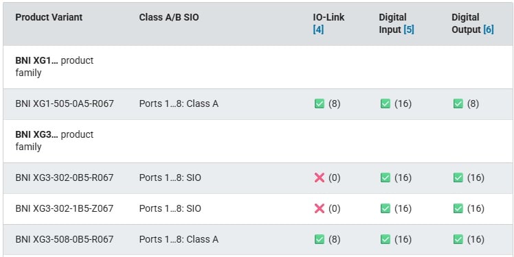
Figure 2. Examine this excerpt from the datasheet: the Balluff XG1 product has 8 total ports. They can all be IO-Link ports. They can all be switched to standard I/O, and each can function as two inputs (16 total), but only one output (8 total). Note the differences in the XG3 family.
Example: Driving a VFD
Chances are, your automation project deals with motors in some way. A VFD might be connected to the fieldbus network (Ethernet, perhaps), but if you’ve just got a few simple on/off VFDs with a locked-in ramp rate and speed, you certainly don’t need to rush out and buy some special IO-Link communication card for this application.
Start/Stop Control
First, connect an M12 cable from a spare port on the IO-Link master. Connect the blue M12 wire to the common ground of the VFD terminals and the black wire to the VFD digital input 1.
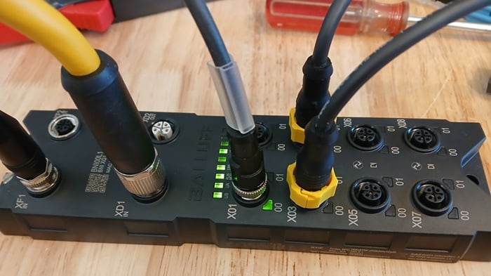
Figure 3. This IO-Link project is using ports X03 and X04 (the M12 cables with the yellow collars).
Change the VFD parameters to accept logical control from the I/O terminals, configured so that input 1 is start/stop. All VFDs can do this; brand and model do not matter.
On the IO-Link master, the tag list contains a configuration block of data. The first byte or two of the configuration data sets the port type (this is fairly universal, but check your model before assuming I’m always correct here). There are usually two bits that must be set per port, one for each pin. That means that [byte 0] : [bits 0 and 1] set the function of pins 4 and 2 of the first port. Then, [bits 2 and 3] set the functions for the next port, and so on. If these bits all hold 0, it’s a standard I/O port. But if they hold a 1, the port is activated for IO-Link.
Change those bit values to 0 for your port.
Now, you can open the output data tags and write 1 into the appropriate bit. In most IO-Link setups, [byte 0] : [bits 0 and 1] write the output status of pins 4 and 2 of the first port. The black wire is pin 4, therefore, we write to bit 0, and the VFD should start.
Note: My setup uses port 3, not port 1. So I use bit 4 instead of bit 0 in the tag list below.
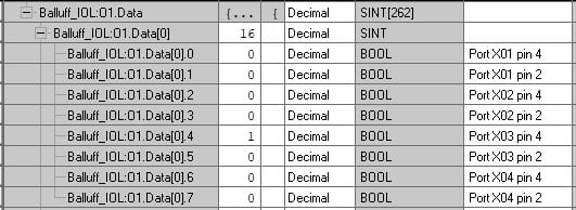
Figure 4. Bits used to drive the standard digital output terminals.
Fwd/Rev Control
If your particular IO-Link master supports two outputs per port, then simply connect the white wire (pin 2) of the M12 cable to the VFD's digital input 2 terminal. This is driven from [byte 0] : [bit 1].
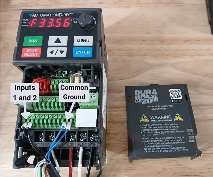
Figure 5. The M12 cables connected to the VFD inputs.
On the other hand, if the IO-Link master only supports one output per port, then you need a second M12 cable connected to the next IO-Link master port. Connect the blue wire to the common ground of the VFD, just like the previous one, and the black wire (pin 4) to the VFD's digital input 2 terminal. This is driven by [byte 0] : [bit 4].
Next, change the VFD parameter so that direction control comes from digital input 2.
All images used courtesy of the author. Some documentation excerpts (modified) from the original manufacturer.