Facebook
 Google
 GitHub
 Linkedin
Tutorial: Commissioning a Balluff BNI IO-Link Master
IO-Link is regarded as a robust field-level network that adds tremendous sensing capability beyond standard analog and digital I/O. Yet it can be difficult to set up. Here’s a guide.
I have been enjoying IO-Link for a couple of years, now having experience with various IO-Link masters and field devices and building them into several PLC systems. Here’s something that the suppliers don’t say out loud: it can be pretty tricky to set up at first.
Although most of the process is similar for all IO-Link masters, this tutorial will explain the steps for adding a Balluff BNI00L1 into a PLC network, from out of the box to reading some sensors in a Rockwell PLC.
A second article will examine a few troubleshooting steps under the hood, including identifying network devices with no display and reading/writing to configuration data that doesn’t exist in the tag list.

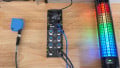
Figure 1. Hardware setup. Image used courtesy of the author
Hardware Setup
We always start with a look at the hardware setup.
I have a Rockwell CompactLogix PLC (L32, so it uses RSLogix 5000; I’m on V20 firmware). IP address is 192.168.1.46. My IP address doesn’t need to match your setup, of course, but it is provided here to illustrate the flat topology of this isolated network.
This is connected via Ethernet cable to the programming PC, and to the Balluff IO-Link master.
The IO-Link device is a BNI00L1, a part of the Balluff ‘black’ line designed specifically for simple, more cost-effective entry into the IO-Link system. It does not have the safety or ingress protection rating of some other product families, but great for I/O.
To power the BNI, use an L-coded M12 cable. Pins 1+4 require 24 volts, pins 2+3 require ground, and pin 5 is earth ground.

Figure 2. M12 power input for the BNI device. Image (modified) used courtesy of Balluff
To test the system, a single IO-Link optical distance sensor will be used (mine is from SICK, but any should work since IO-Link is plug-and-play).
Network Configuration
To add the IO-Link device to the network, you will need to set its own IP configuration before adding it to the project hardware in RSLogix.
Web Server
To set the IP address, you have a couple of options. The simplest option works if you already know the IP address (factory default is 192.168.1.1). Type the IP address into a web browser and you’ll arrive at the web server landing page.

Figure 3. Web server main page. Image used courtesy of the author
Click on the settings button at the top, and you will be prompted to log in.
Default Username: admin
Default Password: printed on the side of the device. Should be a set of 12 uppercase and lowercase letters.
In the network tab, you can set the IP address.

Figure 4. Web server network settings. Image used courtesy of the author
Balluff Engineering Tool (BET)
Earlier, I said, “If you know the IP address…” you can use the web server. If the address is not known or blank, you must use a different tool. Note, however, that there are more than just a few ways to locate unknown devices on any network.
If this is the case, download the Balluff Engineering Tool (BET) from the website. You will need to create a login account, but the account and software are free.
Once the software is open, click on Network on the left sidebar.

Figure 5. Balluff Engineering Tool (BET) for detecting unknown devices. Image used courtesy of the author
Search the network and the device should appear with an IP address, or, as we have established, the field might be blank. Input the proper IP address, confirm, and Write to Device in the bottom corner.
Add the Device to the Project
Balluff provides an electronic datasheet (EDS) to simplify addition to an Ethernet system, like Rockwell’s. The EDS file is found on Balluff’s download page (hint: ctrl+f to search for XG1 and find the right part #).
Install the EDS into RSLogix, and then add it as a new network device in the project tree. Name it (as you want it to appear in your tag list) and input the IP address you set earlier.
Set Ports to IO-Link
Before testing any IO-Link field devices, we need to understand that most ports can function as either normal digital I/O, or they can be more advanced IO-Link data. Standard I/O is the default.
To set the ports to IO-Link function, a configuration bit needs to be set. Per the documentation, this is found in the config tag, byte 0 (:C.Data[0]). Bits 0, 2, 4, etc set the port function to IO-Link.

Figure 6. Tag descriptions (left) and live view of tags and logic in the PLC (right). Image used courtesy of the author
I’m only activating two IO-Link ports in my own setup, so I set bits 0 and 2 using ladder instructions. If you need more, set bits 4 and 6, then repeat for byte [1] if needed.
On my device, the port function did not actually change until I power-cycled the IO-Link master.
Test and Verify
Finally, we can plug in a sensor from any vendor and watch it start collecting data.
Open the tag :I1.Data and the information should show up.
The first 8 bytes are reserved for the states of those default digital I/O ports. If you set all of them to IO-Link, these bytes will all be blank.
For port 0 (the first one), all the data will be in the first few bytes of the 8 to 55 range. The next port picks up at 56. Many of these will be empty of data, but that’s ok because they are designed to be much larger in case some device can send or receive a crazy amount of data, like an IO-Link servo drive, etc.
Table 1. Byte (tag) arrangement for the input data. Image used courtesy of Balluff

In another article, we’ll take a look at some ways to troubleshoot network problems and how to configure some of the parameters under the hood of these IO-Link masters. They can be tricky, but with some understanding, they are extremely useful, capable tools.