Facebook
 Google
 GitHub
 Linkedin
Temp Sensing With RTDs: Wiring Connection and Transmitter Setup
Learn how to measure temperature using an RTD and a temperature transmitter to convert resistance into common analog voltage or current values for process control.
Temperature is a physical parameter used to measure the degree of ‘hotness’ or ‘coldness’ of any object. At the molecular level, temperature depends on the kinetic energy of the molecules of a substance. The molecules of substances are in constant motion. In general, the greater the motion of its molecules, the greater the temperature of a substance. In this context, we say that temperature measures the average kinetic energy of the molecules of the substance.
What is an RTD?
An RTD is a type of sensor used for determining temperature by relating the resistance of the element with temperature. RTD formally stands for resistance temperature detector, and they are also sometimes called resistance thermometers.
How Does an RTD Work?
The materials used in RTD are platinum, nickel, copper, etc. Therefore, an RTD uses either a platinum, nickel, or copper element whose resistance changes with temperature variation. Platinum RTDs are widely used in industrial applications and are called by their periodic table name, Pt: PT100, PT500, and PT1000. The numerals 100, 500, and 1000 represent the resistance values at 0 degrees Celsius.
These sensors, unlike thermocouples, do not generate any signal of their own, either voltage or current. Across the terminals of the RTD, the output is nothing more than an electrical resistance in ohms (Ω). Therefore, using a temperature transmitter, we must convert the RTD’s resistance into a 4-20 mA signal for SCADA/DCS.
Signal transmitters monitor many industrial real-time values like pressure, flow, speed, voltage, current, frequency, temperature, etc., and provide various industry-standard analog signal outputs like 0-10 volts, 0 -5 volts, 0-40 mA, and 4-20 mA. However, a 4-20 mA signal is most commonly used for industrial applications.
In this article, we discuss the transmitters and RTDs; the primary use of these field devices in power plants is to measure and report the following types of temperatures to industrial control systems:
- Generator stator coil temperature
- Stator iron temperature
- Excitation Transformer
- Generator surface cooler temperature
- Transformer winding (R, Y, and B phase) temperature
- Generator Upper and Lower Guide bearing metal temperature
- Thrust bearing oil temperature
- Measuring winding and bearing temperature of electric motors
- Boiler, chiller, and compressor
Types of RTDs: 2, 3, and 4-wire Devices
Practically, RTDs will mostly only be found with 3 types of wiring connection configurations, i.e. 2-wire, 3-wire, and 4-wire. Let's talk about each one in brief before jumping into the practical details.
2-wire RTD
The 2-wire is the simplest configuration of RTD circuit designs. In this scheme, a single lead wire connects each end of the RTD element, exactly as a simple resistor would rest in a circuit.
3-wire RTD
The 3-wire RTD configuration is often used in industry. In this scheme, one extra lead wire is added. The two lead wires are on one side of the element and one lead wire is on the other side. The third wire acts as compensation, used to improve the accuracy.
4-wire RTD
The 4-wire RTD provides an accurate result, combining both the 2 and 3-wire RTD configurations. In this scheme, we have 2 lead wires on both sides of the RTD element to accurately compensate for the resistance of the lead wires, resulting in a measurement of the RTD element alone.
RTD Project Example With a PLC or RTU
The following example will demonstrate the concept of routing a 3-wire RTD through a transmitter to an analog input module.
2-wire Transmitter Connection for mA Output Signal
Figure 1 below shows the wiring scheme, outlining the 3-wire RTDs (right side) connected to the 2-wire transmitter (center column). The output of the transmitter, which is providing 4-20 mA, is further connected to the analog input card of the RTU/PLC (left side), labeled as a ‘connection unit.’

Figure 1. Diagram of 3-wire RTD connections with 2-wire temperature transmitter. The output of the transmitter is connected via Connection Unit DSTA 121
The final connection (shown at the top of the diagram) is the transmitter power supply requirement, 8 to 36 VDC in this case.
The following equipment and software package is used to configure the transmitter to provide the required output to the PLC/RTU.
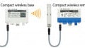
2-wire Universal IPAQ R330
The 3-wire PT100 RTD in our example will be connected to the universal transmitter IPAQ R330 by INOR. This is a modern digital temperature transmitter that supports 2-wire, 3-wire, and 4-wire sensor connections and is compatible with RTDs, thermocouples, and even other variable resistance devices as inputs. This universal transmitter can work with multiple types of RTDs, like Pt100, Ni100, Cu10, etc.

Figure 2. 2-wire IPAQ R330 transmitter. Image used courtesy of INOR
Connection Unit DSTA 120
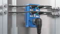
The 2-wire transmitter output is wired to the connection unit DSTA 120 for further processing and control (this is shown in Figure 3 below). The DSTA 120 connection unit is part of the process interface system and is used to bring the raw analog signals to the analog input boards in the control system.
The unit contains the terminal blocks of field wiring for incoming signals. All of the 32 channels are provided with voltage-limiting protective components and a shunt for current signals. The nominal signal range for voltage is +10 V and the current signal range is +20 mA. The 250 Ω shunt is normally used for the adoption of current signals on the connection unit.

Figure 3. Connection Unit DSTA 120 is used for the termination of field wires
Analog Input Card DSAI 120
The DSAI 120 is a plug-in board intended for installation in a rack. The DSAI 120 has 32 input channels for current and voltage signals. The measurement signals are connected to the analog board via a connection unit (the DSTA 120 mentioned previously). The A/D converter works with a 10 V signal.
Installing ConSoft 3 Software
Many temperature transmitters can be configured using the proprietary software, allowing the user to set measurement range, output scaling, and select the sensor type. The transmitter configuration can be performed via a computer COM port connected directly by USB or through a protocol such as HART or Modbus.

Figure 4. USB converter to make a connection between PC and transmitter
To connect and configure the transmitter, first install the ConSoft 3 software on the PC. The installation steps of ConSoft 3 software are given below:

Figure 5. ConSoft 3 software setup steps.
The following snapshots help us configure the R330 transmitter using Consoft software with the following parameters:
Transmitter Type: C/R330
Transmitter Input: 3-wire PT100 sensor
Measuring Range: 0-150 °C
Output: 4-20 mA
Log: enable the log and write the transmitter data in .csv format
Configuring the Temperature Transmitter
- The first step is to click on the Consoft icon, and a new popup window appears to choose the appropriate options as per requirement i.e. reading the configuration of the already configured transmitter, creating a new project, or opening an existing project.

- The second step is to select the transmitter. This project uses the C/R330.

- Now, select the transmitter input, a 3-wire PT100 sensor in our case.

- Under the Function tab, input the measuring range from 0-150 °C.

- The next tab shows the device information like operational hours, loop voltage, serial number, hardware and firmware version, etc.

- Finally, we write the changes to the transmitter (in this case, we have a real-world transmitter and RTD actually connected). Open the last tab, which provides settings for data logging and simulation. Under the Monitor section area, the current temperature value is 51.54 °C, and the output is 9.497 mA.

- We can log the live parameters and save them in a file in the .csv format by clicking the “Start log to file” button.

Temperature Process Data
Using temperature data is critical in most processes, either for monitoring the product or process material, or for monitoring the condition of the devices and equipment for predictive maintenance. Understanding the sensors and transmitters can help you get started on your own sensing process.
All uncredited images used courtesy of the author