The Beginner’s Guide to Automation: Adding Control to the System
Every automated cell requires a ‘brain’ in order to achieve the required tasks. How do you determine the necessary I/O, communication protocols, and processor necessary for controlling your system?
Previously, we have covered the initial steps of choosing the proper automation project and getting started with the initial connections to the real world with sensor integration.
At this point in your project, everything is starting to come together. Your project's concept is moving past planning and visualization, and is progressing toward tangible objects. Some equipment is even starting to be put in place. Now, it's time to tie everything together.
For some, this seems like a daunting task, but if you can understand the types of controls that are necessary within your system, the process can be simplified. This will prevent unnecessary purchases and downtime in developing the controls for your system.
It’s As Easy as One, Two, Three
The first step in determining the correct control for your system is to start by gathering all your equipment and determining their specifications. Everything in your control system will be able to be broken down into inputs, outputs, communication, and controllers. Everything will have to be accounted for in your system.
The first thing that will need to be determined is how many inputs and outputs our entire system will need. When determining inputs and outputs, be sure to document the following items as they will be important in determining components for your control.
- Analog vs. digital signals
- Common digital signal ranges include 5, 12, 24, or 48 volts dc
- Analog signals typically range from 4-20 mA or 0-10 volts
- Sinking (NPN), sourcing (PNP), or configurable between the two
- Motion signals
- Is the signal high-speed?
So, start counting! The best way I found to stay organized is to start with a flowchart of your system and work forward, filling in the blanks. This gives you the best opportunity to find all your currently scoped inputs and outputs, displaying them in a logical sequence. As you are counting, document them in a spreadsheet, or however you deem fit, but keep them organized and separated based on signal type.
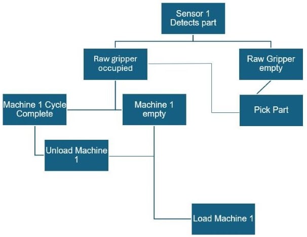
Figure 1. Example of an automation flow chart. Image used courtesy of the author
Now that you know how many inputs and outputs you have, this gives you a baseline for the MINIMUM number that will be required. However, in the automation world, NEVER PLAN FOR THE MINIMUM. There will always be a circumstance that you cannot plan for, and I have heard a lot of “rules of thumb” for I/O ranging from 50% extra to double. However, depending on your system, this can get expensive and can take up a lot of cabinet space.
Here’s what I would personally recommend for most beginners: always have 8 extra contacts and plan for expansion. In other words, your system should have at least 8 remaining I/O and you should leave space in your cabinet for at least two additional I/O modules. If you can plan for that, your cabinet will never get overcrowded, and you will always be able to expand.
Typically, most digital input and output cards will come in 8, 16, or 32 contacts. The cards themselves may be digital or relay, meaning you have either transistor or mechanical contacts. Inputs will also typically be labeled as sinking (for use with NPN) or sourcing (for use with PNP), while some devices are configurable for either.
For a thorough explanation of the difference between sinking and sourcing circuits, check out Sourcing and Sinking for Control System Modules. Also, if you have motion in your system, be sure to verify whether you will need high-speed I/O, commonly used for encoder inputs. Not all contacts support high switching speeds, so ensure you verify exactly what you need in your system.
What About Fieldbus Communications?
In the market right now, there are dozens of different ways to communicate through a network.
So, which network is the right choice? Well, I have some good news and some bad news for you on this subject.
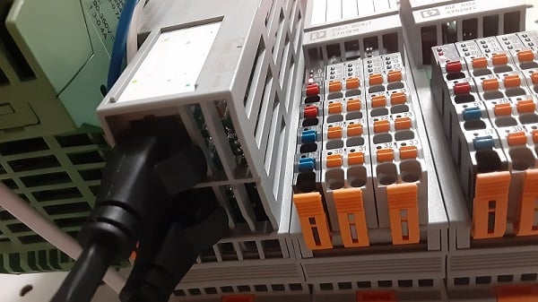
Figure 2. Networking cables on an industrial controller. Image used courtesy of the Control.com engineering team
The good news is that including pretty much any network is a step in the right direction for minimizing the size of your electrical cabinet and reducing the amount of wiring for your system. Field busses are also typically much easier to diagnose and troubleshoot compared to large hard-wired systems. Analog and digital signals can also be transmitted without the use of different modules. Network communication can connect to dozens of nodes as well, for example, Ethernet/IP can connect up to 256 nodes.
The bad news is that 9 times out of 10, the choice of field bus communication will be dictated by the compatibility of the devices that you are installing in your system. You will have to verify the documentation of your devices to determine which protocol will work. For example, Rockwell Automation devices will most likely be controlled through an Ethernet/IP as they actually developed that technology, while a Siemens device will be using PROFIBUS DP/PA. Typical devices will have multiple protocol capabilities or will have a different drive that is compatible with the type of field bus you wish to use.
The advantages of using fieldbus devices vary from application to application, but it is entirely worth using in almost any application. For example, with I/O link devices, copy machines can be set up quickly due to configurations being able to be stored internally and devices can be replaced without programming making repairs quicker. Statuses of machines and devices can be viewed remotely with live feedback. Also, if you’re anything like me, minimizing the overall wiring in any system makes it look cleaner as well.
Choosing the Processor
While there are a great many types of PLCs in the automation world, most fall under two main umbrella categories: fixed (also called brick, or micro) PLCs and modular PLCs.
All controllers function in much the same way, but fixed PLCs tend to be used for smaller applications while modular PLCs will be used for larger applications. For a better explanation of fixed PLCs, check out the article: Introduction to Micro PLCs.
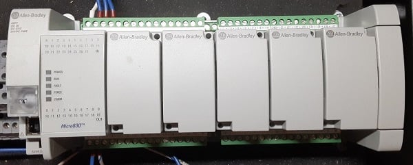
Figure 3. Allen-Bradley Micro830 series PLC. Image used courtesy of the Control.com engineering team
Essentially, fixed PLCs come with a predetermined number of inputs and outputs. Most of the time, I/O will not be able to be extended. I/O for motion will also have to be predetermined as most fixed PLCs will only allow for the connection of variable frequency drives (VFD) or only allow a predetermined number of axes to be connected. Most fixed PLCs will only allow the connection to specific HMIs.
Fixed PLCs tend to be much cheaper than their modular counterparts, although every generation of fixed PLC seems to incorporate a wider range of I/O expandability and adaptability with other equipment.
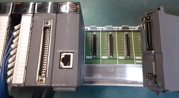
Figure 4. A Mitsubishi modular controller with a backplane and removable modules. Image used courtesy of the Control.com engineering team
Modular PLCs allow for expansion using modules. These modules can be used to support a wide variety of I/O, power supplies, or even communication switches. These are the most convenient when it comes to the expansion of systems. It makes complicated systems easier in the sense that an integrator can include a variety of relay, transistor, or analog signals with just the addition of a simple module.
Next Steps
Once the hardware has been selected, we will discuss the next step which includes the actual commissioning of the system, including identifying and solving problems that will inevitably appear during this phase.