 Facebook
 Google
 GitHub
 Linkedin
Tricks of the Trade: Troubleshooting Industrial Control Cabinets
When the blinking lights on automation devices stop blinking, the control cabinet is often the go-to troubleshooting culprit, but how do you make the best judgments for quickly locating the problem?
Every technician or controls engineer has been in a situation where the status lights on a device within the cabinet are not blinking. You know that, somewhere, the device isn’t receiving power properly, but why? And where do you start looking?
Follow along as I walk through the layout of a control cabinet, explaining the basic guidelines of the mental flowchart that sets you on the path of quickly troubleshooting your problem.

Figure 1. Circuit breakers, power supplies, and contactors in a control cabinet. Image used courtesy of Adobe Stock
Overall Layout of Cabinets
Most commercially designed control panels from UL-listed panel shops are laid out similarly, with the incoming power entering either from the top-right or top-left corner of the panel. This high-voltage power (most likely 3-phase) routes directly into a main disconnect.
After the disconnect, the power will travel into branch fuses or circuit breakers, typically via a distribution block, and then into various control devices such as power supplies, motor drives, and any other AC voltage components.
The AC voltage components are often found on one side of the cabinet, while the DC voltage components are on the other side. This prevents induced voltage from occurring within the cabinet and protects technicians when troubleshooting DC devices vs. AC devices.
After the AC devices have been powered, DC branching protection will be laid out, typically at the top of the DC side of the cabinet. Moving down the panel, you will find relays, contactors, panel I/O, PLCs, amplifiers, and other DC control devices.
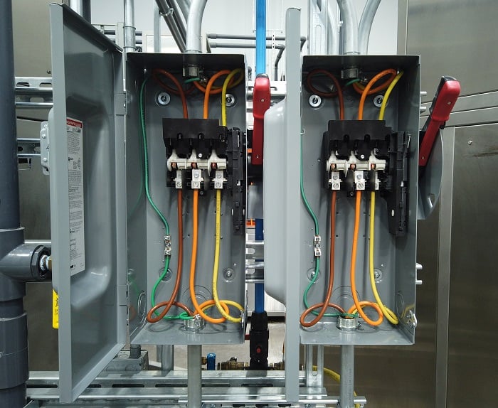
Figure 2. Main disconnect panels with 3-phase supply inputs. Image used courtesy of Adobe Stock
Fused Main Disconnect
Most control cabinets rely on incoming 3-phase power, meaning there are three current-carrying conductors, with each conductor responsible for one phase of the voltage. Each phase is 120 degrees out of sync with either of the other two conductors. In most factories in North America, industrial voltage is either 480 VAC or 600 VAC 3-phase with a 10% deviation.
The first device that the incoming power encounters is the fused disconnect. This serves two purposes: to protect all the downstream devices from an over-current situation and to sever all power entering the control panel when actuated to the open position.
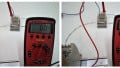
If all power to the control panel is lost, this initial fuse set might be your first spot for troubleshooting. Measuring voltage at the incoming side of the fuse will tell you if there is power entering your panel. If there is a total lack of power, you might have a blown main fuse. This point is akin to the popular troubleshooting question, “is the device plugged in?” It is overlooked surprisingly often.
AC Fuses
The next stop is the AC device or branch protection. Typically, near the top of the panel will be one or more banks of AC fuses or circuit breakers. Fuses may be included in the disconnect device, as explained above, but they might be in a separate fuse block. These protection devices will typically protect one or more devices to isolate power loss, so you might find a fuse block for a bank of VFDs alongside a circuit breaker for a transformer.
Three-phase circuit breakers are made up of single blocks mechanically pinned together to ensure that all three phases open at the same time, and can likewise be reset at the same time. Three-phase fuse blocks are not mechanically linked, so one fuse may rupture without affecting the others.
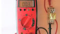
When troubleshooting drives or AC devices, quickly verify the status of all fuses or circuit breakers by testing the voltage to ground for the input and output terminals, both of which should register line voltage (never use a continuity check on a possible live circuit). Many will also include an indicator of some kind to show if the protection device has been tripped. With a 3-phase fuse, one of the three fuses can blow, and the remaining fuses will still be functional, so always check all three fuses with your meter.
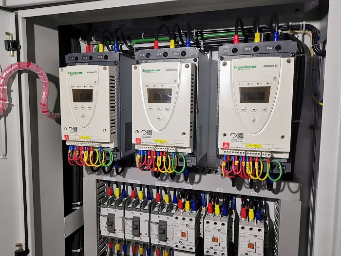
Figure 3. Motor drives (soft starts) installed in a control cabinet. Image used courtesy of Adobe Stock
AC Devices
After the AC protection, the electricity encounters the individual AC devices, including VFDs, servo drives, AC motor starters, power supplies, and transformers. Some of these devices, like the drives, will use both AC motor power and DC control power to function, so if the 3-phase protection device trips, the device may still be powered up in a faulted state.
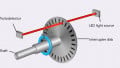
A transformer can convert AC power to DC power if it’s part of a linear power supply, or it can simply step the AC voltage up or down. An indication of a malfunctioned transformer would be a lack of power on downstream devices, or they are faulted due to incorrect voltage from the transformer. You must first determine if the transformer is receiving power at all, so the first step is to check for voltage on the primary side of the transformer (high or low voltage 3-phase), then verify the proper output (usually 115/230 VAC nominal).
DC Power Supply
A DC power supply converts AC power into DC power, so these devices may be located on the AC or the DC side of the cabinet. Various makes and models can support an input of 3-phase power or single-phase power.
Most modern power supplies are quite advanced, with diagnostic features to help troubleshoot issues. A typical status feature is the “DC OK” contact, which is a dry mechanical contact that will close when the power supply is outputting DC power correctly. If the power supply is defective, overloaded, or supplied with incorrect incoming power, the DC OK contact will become open. Running a signal voltage through this contact to a PLC or indicator light can help diagnose problems and raise an alarm instantly.
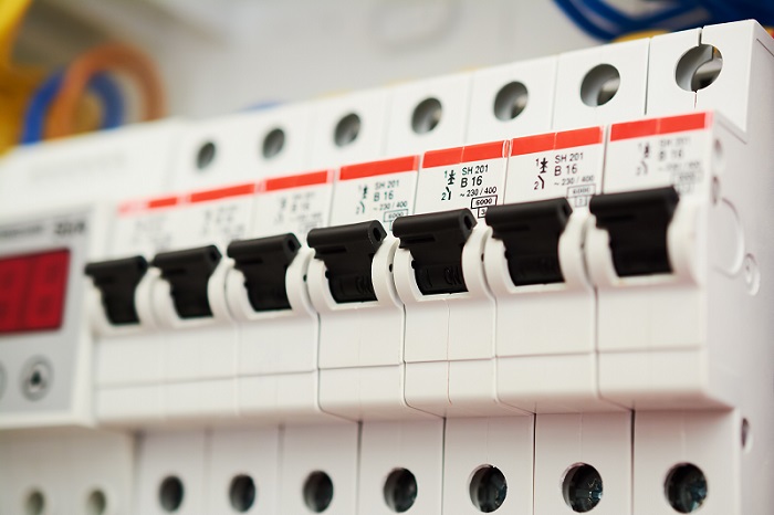
Figure 4. Circuit breakers for branch protection. Image used courtesy of Adobe Stock
DC Branch Circuit Protection
Similar to the circuit protection for the AC side of the panel, the DC components will also require fuses or circuit breakers to protect circuits from over-current events. These devices are usually smaller, like slim miniature circuit breakers and fuses inlaid into DIN rail terminal block holders.
Typically, the DC branch protection will have more devices on each branch compared to the AC protection branches. This is likely due to the lower current consumption of DC devices like valves, relays, and contactors. Most DC protection devices have an indicator that shows when a trip has occurred. As a technician, this is likely where you will spend most of your troubleshooting time.
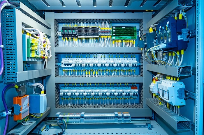
Figure 5. Inside a complex control cabinet. Image used courtesy of Adobe Stock
Troubleshooting Tips
When devices lose power, production comes to a grinding halt and the factory starts losing money, so it is up to the technician to find the problem quickly. Most times the problem is just a failing circuit breaker or fuse that needs to be replaced. Bigger problems require tracing wires to ensure there isn’t a short to ground. When a protection device trips, try resetting it or replacing the fuse first. If it trips again right away, you need to start looking for grounding shorts or damaged wires and cables.
If you are integrating equipment and you trip a protection device, review the current draw on the circuit, the designer or technician may have chosen an incorrect size fuse or circuit breaker for that circuit. Simply look at each device on the circuit and add up the current draw, if the total sum of the current draw is larger than your fuse, check with the designer if you can increase the fuse size or move components onto another circuit.
Don’t Panic And Grab Your Meter
When troubleshooting power issues on electrical devices, always use the proper personal protection equipment, stay calm, and use your meter to trace where the power is or, perhaps more importantly, where it is not.


Very helpful article…