Understanding Binary Numbers in PLCs
This article introduces how the binary system is used in PLC programming and covers why this number system works so well in this area of system control.
Modern control systems almost always use some form of digital control — most often in the form of a PLC. These computers rely on the use and understanding of the binary number format system, although fortunately, they simplify the process for many of us who are not computer scientists. A good programmer still benefits from some understanding of how numbers are used in PLCs.
Most engineers who program PLCs are aware of the binary number format that runs the operation of a computer behind the scenes.
In normal personal computers, most of the numbers are converted into our standard base-10 system, so most normal users can get away without understanding binary at all. In contrast, a PLC is made to interface with a wide variety of input and output devices, and this makes it necessary to understand the basics of how the computer numbering system works.
Why Does Binary Work so Well for PLC Programming?
Binary is a counting system that works if there are only two possible numerical options to choose from. Unlike our decimal base-10 system where we have 0 through 9, binary only has 0 and 1. This is necessary for computers because of the transistors in the processor which can only be on or off.
In an industrial control system, this is also reflected in the field devices, most of which are sensors that provide on/off data, or outputs such as lights and relays which are also limited to on/off. Since every PLC system contains at least a few of these devices, understanding the numbering is essential.
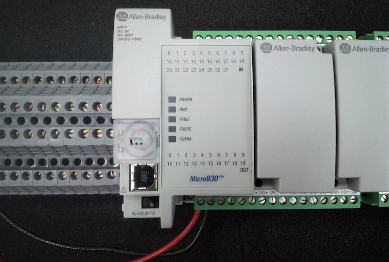
Figure 1. An Allen Bradley Micro 830 PLC. This processor is capable of storing up to 20 kilobytes of data, limited enough that understanding of data consumption is very important.
A single binary number, either on or off, is called a ‘bit’. Normally, bits are combined in the processor in order to use and store data more efficiently, since it is rare for any program to contain only a single bit. Most modern PCs combine the bits in groups of 32 or 64, unsurprisingly called 32-bit or 64-bit computers. For faster operation with big programs, a 64-bit structure is more efficient.
However, in an industrial system, programs are often not as large and most of the data is smaller in size, so it is unnecessary to strive for the largest continuous bit sizes possible. Most PLCs will be 32-bit, some older ones are 16-bit. This bit structure is the basis for addressing the individual registers.
Addresses, Registers, and Tags
An easy way to understand registers is to think of a parking garage. Each space has its own number, or ‘address’. Each space is designed for a bus that can hold 16 or 32 people, depending on the bit structure.
To hold the same amount of data, a 16-bit machine will need twice as many registers and addresses. It also takes twice as long to access all the registers in a 16-bit machine. So it’s much more efficient and faster to use 32 bits than 16. For this article, we’ll assume we’re discussing a 32-bit processor which is common for Rockwell, Siemens, and Automation Direct PLCs, and most others.
When you create a new tag to represent real-life data in the PLC, you have used up one of those parking spaces. It doesn’t matter whether you drive a bus or a motorcycle, you have still used up the entire parking space. Likewise, when you create a tag in the form of a single bit (boolean) or a 32-bit integer, you’ve still used up an entire address and consumed 32 bits of memory (or 4 bytes). This means that you might as well use 32-bit integers as a default, a strategy which many programs already implement.
If you find yourself creating numerous boolean values as flags or memory coils, it might be more space effective to create an entire 32-bit integer, then simply reference the bits of that integer. For example, create an integer (or DINT, or Double) called MemoryCoil, then use MemoryCoil.0 or MemoryCoil.1 as needed. This obviously would require very careful attention to detail, but for every 32 coils used, you would only consume 1 ‘parking space’ register instead of 32. This would save 124 bytes of space.
Inside a PLC, data will most often consist of either those single-bit Boolean values such as a sensor or a latching memory bit, or it might be larger integer numbers such as a counter preset or timer current value. The type of integer chosen might cause a limitation in what can be accomplished. Bits and integers of different sizes can each store a different maximum value, as shown in Table 1 below.
| Number of Bits | Value Range | Common Names | |
| Single Bit | 1 | 1 | BOOL, Boolean, Bit |
| Integer | 8 | -128 to 127 | SINT, Short, Byte |
| Integer | 16 | -32,768 to 32,767 | INT, Integer, Word |
| Integer | 32 | -2.15 Billion to 2.15 Billion* | DINT, Double Integer, Double Word, Long |
*The last value is not precisely 2.15 billion, this is simply listed to give an idea of how massive the value truly is.
There are a couple of exceptions to the list above that may sometimes appear. This table lists the standard values which can swing from positive to negative. This is useful when working with values such as temperatures, pressures, offsets from a point, etc which all might be negative or positive.
For other values, such as the accumulation of a timer or the length of an object, there will never be a negative value. In these cases, there may be ‘unsigned’ integers which count up to twice the value of the signed ones. They just can’t hold negative values.
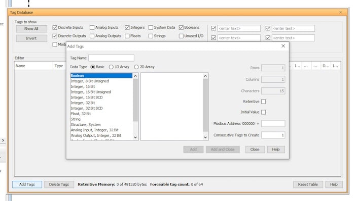
Figure 2. A sample of data creation from Automation Direct. A listing of possible data types can be seen on the menu.
There is a final category —those with decimal points — that is best addressed separately. These are often called ‘float’ or ‘Real’ and are commonly attached to analog inputs. They still consume 32 bits, but the structure is different and might confuse the subject of integers which is the purpose of this article.
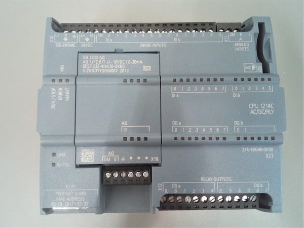
Figure 3. A Siemens S7-1200 PLC. This processor is 32-bit and has a maximum active program (work memory) size of 100 kilobytes — not a lot of space to spare.
Why Don’t We See 64-bit PLCs?
Industrial processors are always trying to find the perfect balance between speed and efficient use of memory. Certainly, a 64-bit PLC would be much faster and would have access information faster, since it has fewer register addresses to sort through.
However, each time you create a new tag, it would consume twice as much memory (64 bits, or 8 bytes). You would use up the total allotted memory much faster. This might be fine if the data you want to store consists of huge files, but this isn’t reality - it’s mostly single-bit field devices. We have absolutely no reason to use up 64 bits for every boolean value we need to create.