 Facebook
 Google
 GitHub
 Linkedin
Using Loop Powered Isolators to Solve Ground Loop Problems
Many signal sources and process transmitters do not include isolation, which can cause problems when the instruments are at different locations. A loop powered isolator is often the solution.
Ground loops can cause problems. A system with no input/output (galvanic) isolation may be fine when everything is at the same location, but suddenly develop ground loop problems when the system is separated. For instance, the “ground” at one location may not be the same as at a different location. Sometimes they could even be from two different power circuits. Even if the ground point is nominally the same, the AC interference and noise will probably be different.
Adding isolation to an already-complete system can sometimes be a big problem. You might have to remove, rearrange, add a new component or two, and rewire everything. It could be even more difficult if the grounds are at two different power locations. There’s no easy answer, but if you’re dealing with a 4-20 mA system, you sometimes can use a loop powered isolator to make the job easier.
What is a Loop Powered (4-20 mA) Isolator?
A loop powered isolator is a device that takes the input, adds isolation and provides the same exact output current. The output is taken from the input power: no other power is needed. The power comes in the form of a voltage loss. The output current is the same as the input, but the voltage is a few volts less.
This is useful for constant current sources, since the voltage drop is compensated by an equal rise in the source voltage.
How Does a Loop Powered Isolator Work?
The isolation factor involves adding a transformer to the circuit. You first have to add a chopper to convert the DC to AC. You next add the transformer, and then convert the output back to DC. See Figure 1.

Figure 1. A loop powered isolator chops the DC signal to AC, adds a transformer for isolation, then turns it back to DC. Circuitry is added to make the output precisely equal to the input.
The details are not as easy as it would at first seem, though. All transformers have losses. If you were to use a 1:1 transformer, the output current would be a bit lower than the input. The current needs to be increased a bit, reducing the total voltage. Also, the losses change as the resistance changes. If everything is ok at, say, 100 ohms, the losses will change at 200 or 500 ohms. Even if the resistance remains constant, the linearity might be degraded by the change of voltage as the current increases or decreases.
Normally, the losses grow as the resistance increases. It takes additional circuitry to keep the output the same. You also need to filter the output.
An Important Detail
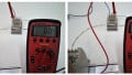
The output voltage will drop a few volts, typically about 7 V at zero ohms and increasing to maybe 14 to 18 V at 500 ohms. Some of the newest devices require fewer lost volts. Not all isolators specify the voltage drop, since a relatively small drop will not really affect the performance of the current source.
Applications of Isolators
More about ground loops. Ground loops can cause different types of problems. If everything is at the same location, the problem usually is due to interference and noise. If the locations are not the same, you might also have DC problems if the actual earth grounds are different. For instance, the DC potential of one earth ground might be slightly different than another.
A different problem occurs when two different voltages end up being connected to the same circuit. Probably the most common problem is when thermocouples are involved. You might think that the thermocouple is grounded, but in fact, the thermocouple junction is at something other than zero. That would be true even if one thermocouple was located right next to the other.
Isolator Details and Specifications
Typical specifications include:
Input/Output Isolation: Typically 1,000 or 1,500 volts RMS.
Maximum Input Voltage: Typically 35 V maximum.
Accuracy: Typically 0.1% or better.
Linearity: Typically 0.1% or better.
Load Variation Effect: Typically 0.1% or better, 0-500 ohms.
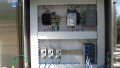
All the companies we are aware of use a 35 mm DIN rail to mount it, although the details differ. Here are two examples:

Figure 2. Comparison of two different loop powered isolators. Images used courtesy of Absolute Process Instruments and Phoenix Contact
Is Isolation Really Necessary?
Often, systems work fine without isolation. Other times you may already know that isolation is likely, and plan accordingly. In that case, the best option will sometimes be to add a loop powered isolator.
Sometimes, though, you may find unexpected problems. When that happens, your best or easiest solution often will be a loop powered isolator. It involves the fewest number of parts and needs no added power supply.
Featured image (modified) used courtesy of Omega Engineering


I assume the input side is loop powered and that the output side is not an active 4-20mA output and the output needs a loop power supply as well. Correct?