Facebook
 Google
 GitHub
 Linkedin
What are Interposing Relays in Control Circuits?
An interposing relay is an interface between a control system and a higher power circuit to provide isolation or amplification of mismatched voltage and current from a control to a load circuit.
A reliable definition of a relay is ‘a combination of both monitoring and sensing devices.’ A relay is operated by a variation of conditions in one electrical circuit (the control) to affect the operation of electric devices in the same or another electrical circuit (the load).
| Check out our exclusive ebook: The Complete Guide to Relays! |
What is an Interposing Relay?
An interposing relay is simply an auxiliary relay, primarily used in control and instrumentation circuits, to interface, isolate, or separate two different circuits or devices. The relay components include a coil that is energized by a DC power source used to activate the relay contacts (normally opened or normally closed) to trigger another circuit.
It is important to know that interposing relays differ from protective and control relays, each serving different functions and roles in power and control systems. The principal function of the protective relay is to protect service from interruption or prevent damage to equipment. A control relay performs logic task handling, often replaced by a PLC in modern control systems.
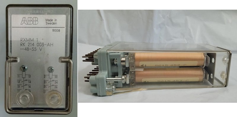
Figure 1. Front and side view of ABB RXMM 1 relay with 2x coils, each with 3x NO contacts with rated voltage 48-55 VDC, for applications where few contacts are needed.
Interposing relays can be charged with different voltages and, likewise, the various contacts can be used for different voltage levels. Engineers can design versatile and safe circuits and logic for controlling and operating electrical equipment. The most important key parameters that need to be considered while selecting interposing relays for the target circuit are:
- The voltage that will be used to energize the coil must be matched with the control circuit voltage: 24/50/230 VDC or 115/230 VAC.
- The number and the current and voltage ratings of the interposing relay contacts must at least equal the load circuit demands.
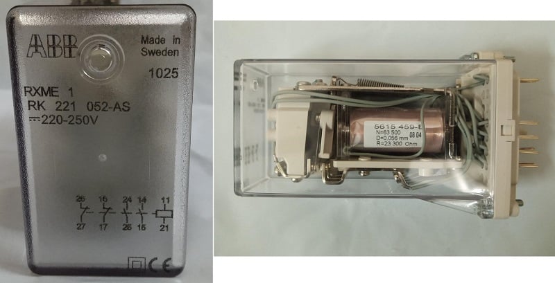
Figure 2. ABB RXME 1 relay with rated DC voltage 220-250 V with 4x heavy-duty contacts: 2x NO and 2x NC.
How are they used with DI and DO?
In a power generation plant, the data acquisition comprises three types of data: analog, discrete, and pulse data. Often in SCADA/DCS, the field signals are terminated in marshaling panels to control and monitor the power plant equipment and report statuses like a limit switch on/off, start/stop, feedback, pumps, isolators, breakers, or tape changer positions.
Indications are connected locally to the digital input board in the terminal (RTU). Reporting of a new status of an indication is performed when one of the following conditions is satisfied:
- The indication has changed status, for example, a breaker changing from open to closed.
- The indication has been activated.
- Cold start or warm start of the RTU/PLC/Controller.
Another type of information from the control center to a terminal is the commands. The terminal command outputs are intended to control an object in the local plant or the remote control equipment directly or via intermediate relays.
In the case of these voltages in signal marshaling panels, we see how the isolation works between two voltage levels. Suppose we need to operate a device that needs 120 AC, but the PLC can only output 24 VDC. In this case, the interposing relay coil would be energized with 24 VDC. As a result, the relay contacts will operate (close) to carry the 120 VAC to operate the device. In simple words, we use small voltage to control high-voltage devices.
In this scenario, the interposing relay also provides some sort of protection to the expensive PLC from the voltage surge from the other side. In the worst-case scenario, the relay might be damaged due to surge and in that case, we simply need to replace it.
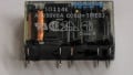
Figure 3. Phoenix Interposing relay 220 VAC/DC with a single NO contact.
The wiring diagram in Figure 4 shows how interposing has been used between the two different voltage level circuits to send the status of the voltage regulation mode “Auto/Manual” to the digital input board of the controller. The right side circuit is operating on the 230 VDC to energize the relay coil. When the relay coil energizes, its NO (normally open) contact becomes closed, and the 48 VDC circuit passes through the relay contact to make the DI channel high on the left side.
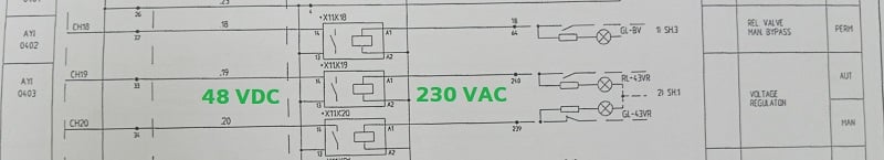
Figure 4. Hardwired wiring diagram, the interposing relay used to report the mode of “voltage regulation Auto/Manual” to SCADA
Advantages of Interposing Relays
- As stated above, the interposing relays connect two systems working on different voltage levels, which can protect the control system side when the other side gets damaged due to some short circuit.
- Well-suited for interlocking, protection, and isolation of industrial control systems with a variety of ratings and contact specs.
- The most economical and safe interface between the low voltage control components and high voltage operating devices like pump motors.
- The interposing relay coil can be energized on low voltage and the contact of the relays can be used for circuits operating on high voltage and high current.
- Provides isolation between the circuits from voltage spikes.
- A single relay can be used to control multiple circuits or other relays by operating several NO/NC contacts used in different circuits.
Summary
The role of interposing relays in the control circuit is to interface two different voltage-level circuits to ensure compatibility and isolation. From a safety perspective, interposing relays prevent damage to sensitive components by handling higher loads. The common applications of interposing relays include interlocking, protection, status reporting, and operating equipment through commands.
The selection parameters for the engineer to select relays are voltage ratings, contact configurations, and environmental conditions to help choose the best relay for each application.
All images used courtesy of the author