Facebook
 Google
 GitHub
 Linkedin
Measuring Electrical Conductivity
The electrical conductivity of liquids is an important analytical measurement in many industrial processes. This measurement is one of the more non-specific types of analytical technologies, because it does not discriminate between different conductive substances dissolved in the solution. For this reason, conductivity measurement is found in process applications where the type of conductive substance is irrelevant (e.g. ultra-pure water treatment for semiconductor “chip” manufacturing, where any conductive substance dissolved in the water is undesirable), or where the substance of interest is known to be the only conductive substance present in significant quantity (e.g. controlling the salinity of a brine solution, where large quantities of salt are added to water).
Electrical conductivity in metals is the result of free electrons drifting within a “lattice” of atomic nuclei comprising the metal object. When a voltage is applied across two points of a metal object, these free electrons immediately drift toward the positive pole (anode) and away from the negative pole (cathode).
Electrical conductivity in liquids is another matter entirely. Here, the charge carriers are ions: electrically imbalanced atoms or molecules that are free to drift because they are not “locked” into a lattice structure as is the case with solid substances. The degree of electrical conductivity of any liquid is therefore dependent on the ion density of the solution (how many ions freely exist per unit volume of liquid). When a voltage is applied across two points of a liquid solution, negative ions will drift toward the positive pole (anode) and positive ions will drift toward the negative pole (cathode). In honor of this directional drifting, negative ions are sometimes called anions (attracted to the anode), while positive ions are sometimes called cations (attracted to the cathode).
Electrical conductivity in gases is much the same: ions are the charge carriers. However, with gases at room temperature, ionic activity is virtually nonexistent. A gas must be superheated into a plasma state before substantial ions exist which can support an electric current.
Dissociation and ionization in aqueous solutions
Pure water is a very poor conductor of electricity. Some water molecules will “ionize” into unbalanced halves (instead of H\(_{2}\)O, you will find some negatively charged hydroxyl ions (OH\(^{-}\)) and some positively charged hydrogen ions (H\(^{+}\)), but the percentage is extremely small at room temperature.
Any substance that enhances electrical conductivity when dissolved in water is called an electrolyte. This enhancement of conductivity occurs due to the molecules of the electrolyte separating into positive and negative ions, which are then free to serve as electrical charge carriers. If the electrolyte in question is an ionically-bonded compound (table salt is a common example), the ions forming that compound naturally separate in solution, and this separation is called dissociation. If the electrolyte in question is a covalently-bonded compound (hydrogen chloride is an example), the separation of those molecules into positive and negative ions is called ionization.
Both dissociation and ionization refer to the separation of formerly joined atoms upon entering a solution. The difference between these terms is the type of substance that splits: “dissociation” refers to the division of ionic compounds (such as table salt), while “ionization” refers to covalent-bonded (molecular) compounds such as HCl which are not ionic in their pure state.
Ionic impurities added to water (such as salts and metals) immediately dissociate and become available to act as charge carriers. Thus, the measure of a water sample’s electrical conductivity is a function of its ionic impurity concentration. Conductivity is therefore an important analytical measurement for certain water purity applications, such as the treatment of boiler feedwater, and the preparation of high-purity water used for semiconductor manufacturing.
It should be noted that conductivity measurement is a very non-specific form of analytical measurement. The conductivity of a liquid solution is a gross indication of its ionic content, but it tells us nothing specific about the type or types of ions present in the solution. Therefore, conductivity measurement is meaningful only when we have prior knowledge of the particular ionic species present in the solution (or when the purpose is to eliminate all ions in the solution such as in the case of ultra-pure water treatment, in which case we do not care about types of ions because our ideal goal is zero conductivity).
Two-electrode conductivity probes
We may measure the electrical conductivity of a liquid solution by passing an electric current through it. The most primitive form of conductivity sensor (sometimes referred to as a conductivity cell) consists of two metal electrodes inserted in the solution, connected to a circuit designed to measure conductance (\(G\)), the reciprocal of resistance (\(1 \over R\)):
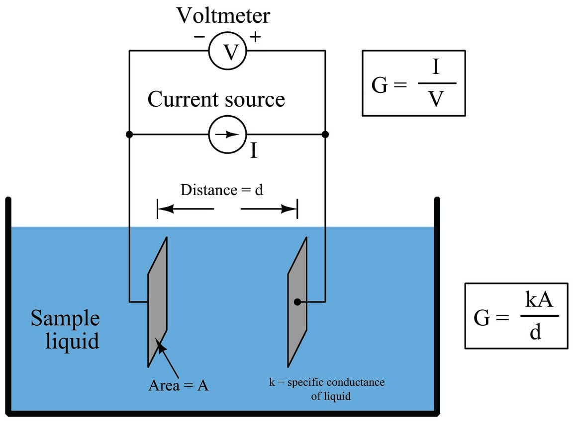
A general problem faced with electrical measurements of liquid conductance is that the derived conductance value (\(G\)) does not tell us much about the liquid itself, because that measurement depends just as much on the geometry of the plates (their area \(A\) and separation distance \(d\)) as it does on the ionic activity of the liquid solution. If we are trying to analyze the liquid all by itself, what we really need is a measurement of specific conductivity (\(k\), or conductance) independent of plate geometry.
We face the same essential problem when trying to quantify the resistivity of metal conductors. If we measure the resistance of a piece of wire in the same manner shown in the previous illustration measuring liquid conductance, we arrive at a result that is every bit as much dependent on the length and area of the wire specimen as it is on the resistivity of the metal itself:
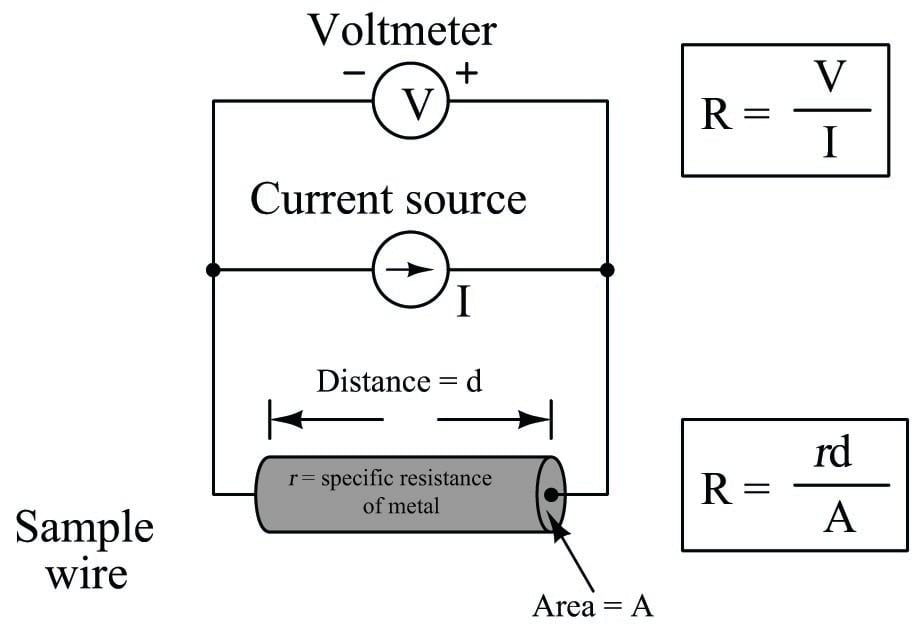
In other words, the calculated value in ohms (from direct voltage and current measurements) for the resistance of this metal specimen doesn’t tell us much about that type of metal in general, but rather it tells us the resistance of that particular specimen of wire. In order to calculate the specific resistance (\(\rho\), or resistivity) of the metal, we must also account for the specimen’s length (\(d\)) and cross-sectional area (\(A\)).
The mathematical relationship between conductance (\(G\)), plate area (\(A\)), plate distance (\(d\)), and the actual conductivity of the liquid (\(k\)) is expressed in the following formula:
\[G = k{A \over d}\]
Where,
\(G\) = Conductance, in Siemens (S)
\(k\) = Specific conductance (conductivity) of liquid, in Siemens per centimeter (S/cm)
\(A\) = Electrode area (each), in square centimeters (cm\(^{2}\))
\(d\) = Electrode separation distance, in centimeters (cm)
Manipulating this formula to solve for conductivity (\(k\)) of the liquid:
\[k = {Gd \over A}\]
The unit of Siemens per centimeter for liquid conductivity may seem odd at first, but it is necessary to account for all the units present in the variables of the equation. A simple dimensional analysis proves this:
\[k = {Gd \over A} \hskip 30pt \left[{\hbox{S} \over \hbox{cm}}\right] = {[\hbox{S}] [\hbox{cm}] \over [\hbox{cm}^2]}\]
In order to quantity the plate geometry for any particular cell, manufacturers typically express the fraction \(d \over A\) as a single value called the cell constant, symbolized by the Greek letter “theta” (\(\theta\)) and expressed in the unit of inverse centimeters (cm\(^{-1}\)):
\[\theta = {d \over A} \hskip 30pt \left[{1 \over \hbox{cm}}\right] = \left[\hbox{cm}^{-1}\right] = {[\hbox{cm}] \over [\hbox{cm}^2]}\]
Substituting \(\theta\) for the quotient \(d \over A\) in the conductivity formula reveals conductivity to be the simple product of measured conductance (\(G\)) and the cell constant:
\[k = G \theta\]
Where,
\(k\) = Specific conductivity of liquid, in Siemens per centimeter (S/cm)
\(G\) = Conductance, in Siemens (S)
\(\theta\) = Cell constant, in inverse centimeters (cm\(^{-1}\))
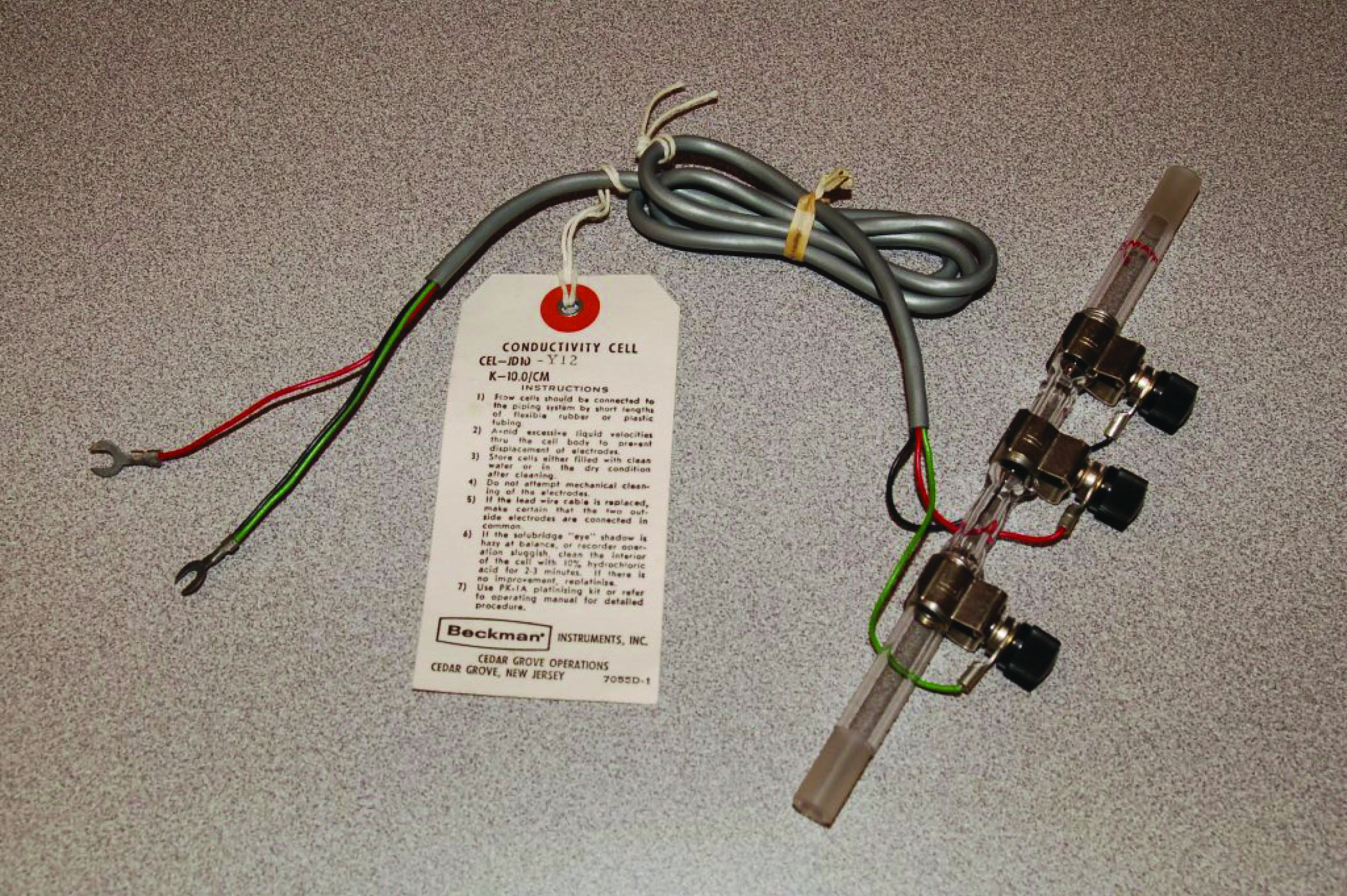
The following photograph shows an example of such a direct-contact style of conductivity probe, consisting of stainless steel electrodes contacting the fluid flowing through a glass tube:
Two-electrode conductivity cells are not very practical in real applications, because mineral and metal ions attracted to the electrodes tend to “foul” the electrodes over time forming solid, insulating barriers on the electrodes. While this “electroplating” action may be substantially reduced by using AC instead of DC to excite the sensing circuit, it is usually not enough. Over time, the conductive barriers formed by ions bonded to the electrode surfaces will create calibration errors by making the instrument “think” the liquid is less conductive than it actually is.
Four-electrode conductivity probes
A very old electrical technique known as the Kelvin or four-wire resistance-measuring method is a practical solution to the problem of electrode fouling faced by two-electrode conductivity probes. Commonly employed to make precise resistance measurements for scientific experiments in laboratory conditions, as well as measuring the electrical resistance of strain gauges and other resistive sensors such as RTDs, the four-wire technique uses four conductors to connect the resistance under test to the measuring instrument:
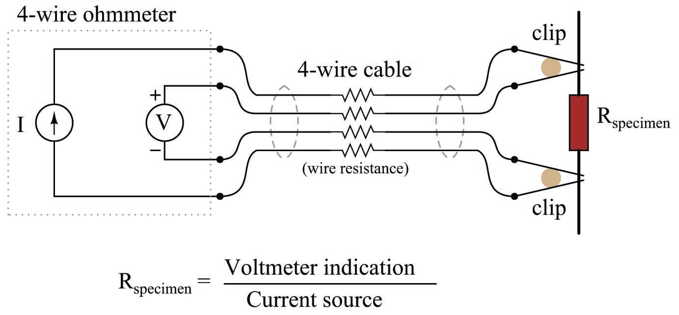
Only the outer two conductors carry substantial current. The inner two conductors connecting the voltmeter to the test specimen carry negligible current (due to the voltmeter’s extremely high input impedance) and therefore drop negligible voltage along their lengths. Voltage dropped across the current-carrying (outer) wires is irrelevant, since that voltage drop is never detected by the voltmeter.
Since the voltmeter only measures voltage dropped across the specimen (the resistor under test), and not the test resistance plus wiring resistance, the resulting resistance measurement is much more accurate than if only two wires were used to connect the test meters to the specimen.
In the case of conductivity measurement, it is not wire resistance that we care to ignore, but rather the added resistance caused by fouling of the electrodes. By using four electrodes instead of two, we are able to measure voltage dropped across a length of liquid solution only, and completely ignore the resistive effects of electrode fouling:
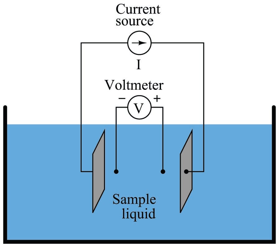
In the 4-wire conductivity cell, any electrode fouling will merely burden the current source by causing it to output a greater voltage, but it will not affect the amount of voltage detected by the two inner electrodes as that electric current passes through the liquid. Any fouling that happens to occur on the two inner electrodes is of no effect to our conductivity measurement because these inner electrodes carry negligible current. With little or no current through the inner electrodes, there will be negligible voltage dropped across any resistive coating that happens to form on them, and thus the voltmeter will still register the true voltage dropped by the liquid solution.
If the solution’s conductivity is defined as the product of the measured conductance and the cell constant (\(k = G \theta\)), and conductance is defined as the ratio of current to voltage (\(G = {I \over V}\)), then we may determine conductivity from voltage and current measurements by combining these two equations:
\[k = G \theta \hskip 30pt G = {I \over V}\]
\[\hbox{\textit{. . . substituting} } {I \over V} \hbox{\textit{ for }} G \hbox{\textit{ . . .}}\]
\[k = {I \over V} \theta \hskip 15pt \hbox{or} \hskip 15pt k = {{I \theta} \over V}\]
Some conductivity instruments employ a second voltmeter to measure the voltage dropped between the “excitation” electrodes, to indicate electrode fouling:
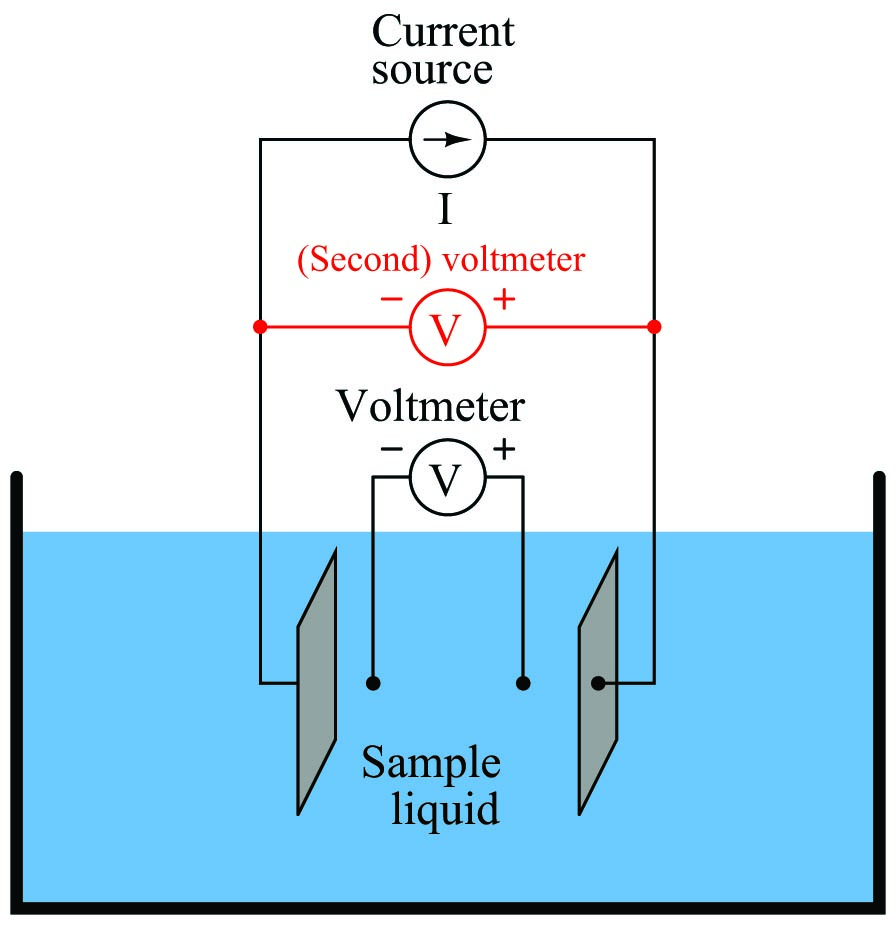
Any form of electrode fouling will cause this secondary voltage measurement to disproportionately exceed the first, thus providing an indicator that instrument technicians may use for predictive maintenance (telling them when the probes need cleaning or replacement). Meanwhile, the primary voltmeter will do its job of accurately measuring liquid conductivity so long as the current source is still able to output its normal amount of current.
Electrodeless conductivity probes
An entirely different design of conductivity cell called electrodeless uses electromagnetic induction rather than direct electrical contact to detect the conductivity of the liquid solution. This cell design enjoys the distinct advantage of virtual immunity to fouling, since there is no direct electrical contact between the measurement circuit and the liquid solution. Instead of using two or four electrodes inserted into the solution for conductivity measurement, this cell uses two toroidal inductors (one to induce an AC voltage in the liquid solution, and the other to measure the strength of the resulting current through the solution):
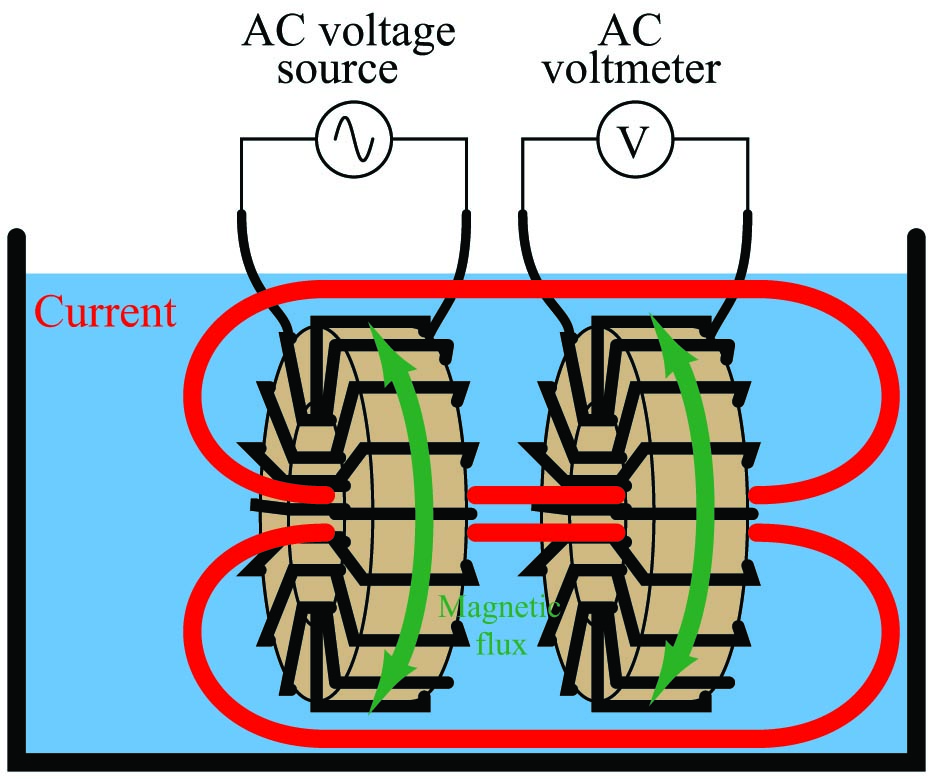
The basic idea of this instrument is that a primary coil energized by AC power induces an electric current that passes through the sample liquid. This current, in turn, induces a measurable voltage in a secondary coil. Since ferromagnetic toroids do an excellent job of containing their own magnetic fields, there will be negligible mutual inductance between the two wire coils. The only way a voltage will be induced in the secondary coil is if there is an AC current passing through the center of that coil, through the liquid itself. If the liquid is non-conductive, the secondary coil will see no induced voltage at all despite being situated near the energized primary coil. The more conductive the liquid solution, the more current will pass through the center of both coils (through the liquid), thus producing a greater induced voltage at the secondary coil. Secondary coil voltage therefore is directly proportional to liquid conductivity.
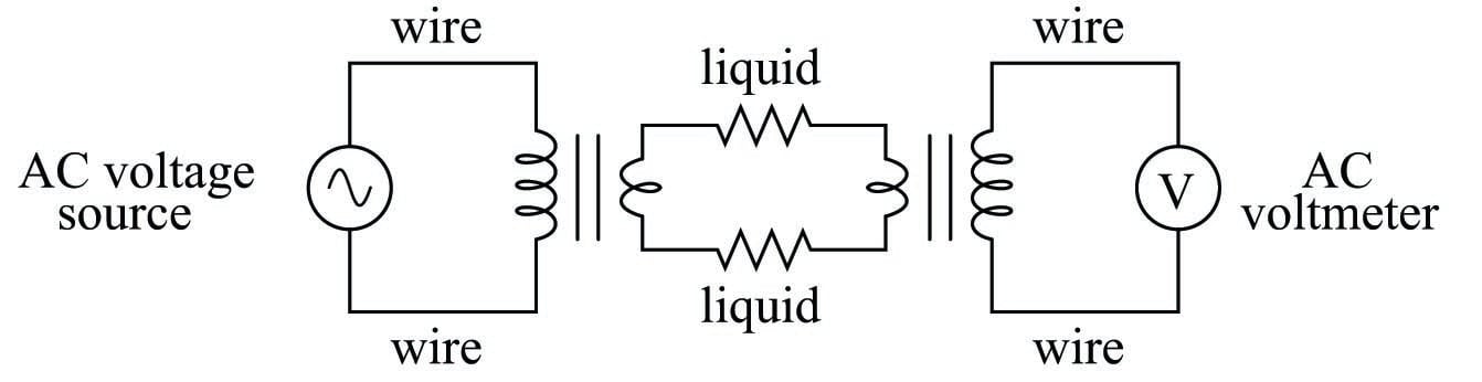
The equivalent electrical circuit for a toroidal conductivity probe looks like a pair of transformers, with the liquid acting as a resistive path for current to connect the two transformers together:
Toroidal conductivity cells are preferred over direct-contact conductivity cells whenever possible, due to their ruggedness and virtual immunity to fouling. However, toroidal cells are not sensitive enough for conductivity measurement in high-purity applications such as boiler feedwater treatment and ultra-pure water treatment necessary for pharmaceutical and semiconductor manufacturing. As always, the manufacturer’s specifications are the best source of information for conductivity cell applicability in any particular process.
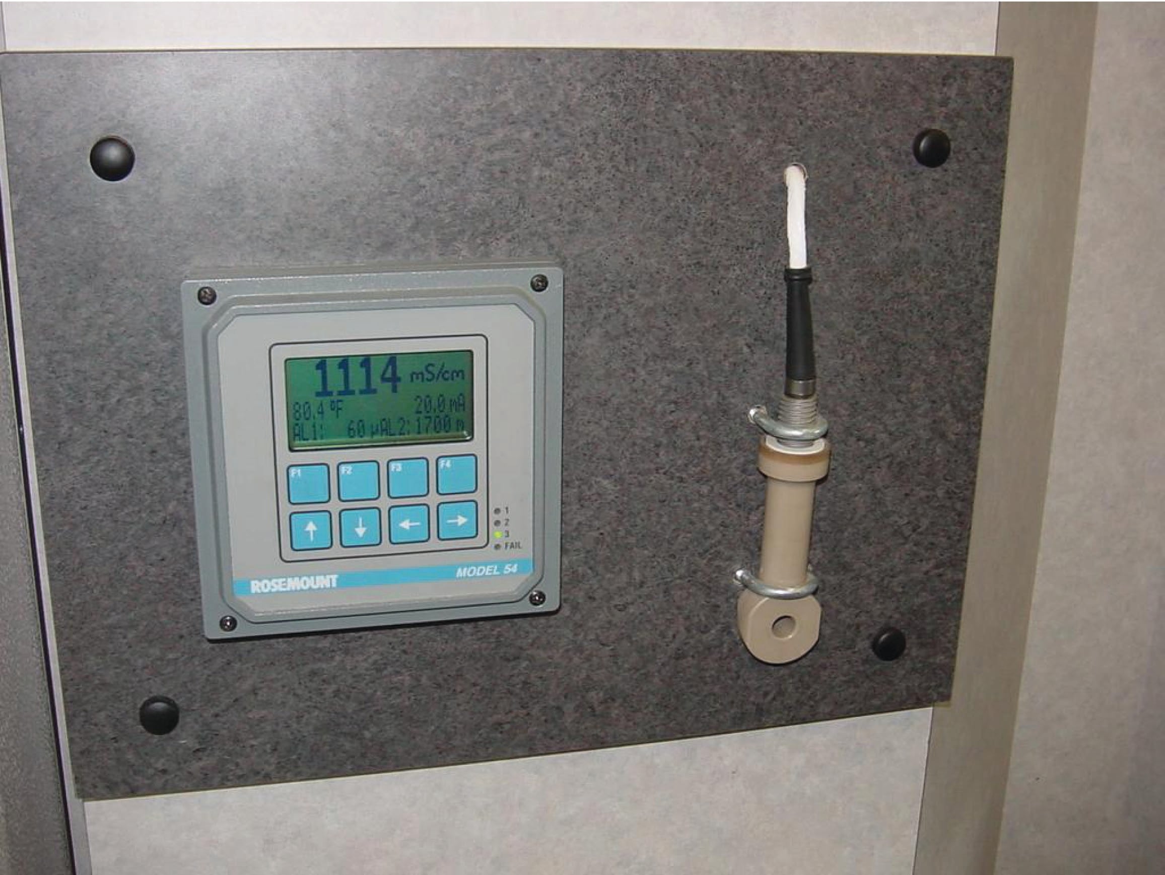
The following photograph shows a toroidal conductivity probe mounted on a display board at a trade-show, along with a conductivity transmitter (to both display the conductivity measurement in millisiemens per centimeter and also transmit the measurement as a 4-20 mA analog signal):