 Facebook
 Google
 GitHub
 Linkedin
Fluorescence Measurement
When a high-energy photon strikes an atom, it may eject one of the lower-level electrons from its shell, leaving a vacancy to be filled by one of the electrons already residing in a shell higher than the vacancy but lower than that of the ejected electron. When that medium-level electron falls down to fill the vacancy, it emits a photon of less energy than the one responsible for ejecting the original electron. Thus, a high-energy photon strikes the atom, and in turn, the atom releases a low-energy photon. This phenomenon is known as fluorescence.
The relationship between a photon’s energy and its frequency (and correspondingly, its wavelength) is a well-defined proportionality of Planck’s constant \(h\):
\[E = hf \hbox{\hskip 50pt or \hskip 50pt} E = {hc \over \lambda}\]
Where,
\(E\) = Energy carried by a single “photon” of light (joules)
\(h\) = Planck’s constant (6.626 \(\times\) \(10^{-34}\) joule-seconds)
\(f\) = Frequency of light wave (Hz, or 1/seconds)
\(c\) = Speed of light in a vacuum (\(\approx\) 3 \(\times\) \(10^8\) meters per second)
\(\lambda\) = Wavelength of light (meters)
Therefore, the high-energy photon necessary for ejecting a low-level electron from an atom must be a photon of high frequency (short wavelength), and the low-energy photon emitted by the atom must be one of low frequency (long wavelength).
Photons carrying sufficient energy to eject low-level electrons from atoms typically exist in the ultraviolet range and above. The lower-energy photons emitted by the excited atoms often fall within the visible light spectrum. Thus, what we see here is a mechanism for ultraviolet (invisible) light to cause a substance to glow with visible colors.
Fluorescence is commonly used for entertainment purposes in the form of a black light: an electrical bulb designed to emit ultraviolet light. Many different organic compounds readily fluoresce under such a light source, producing an eerie glow. Chemical substances present in a white paper, certain inks, and certain types of clothing detergents exhibit strong fluorescent properties, as do many bodily fluids. In fact, the presence of fluorescent compounds in paper, inks, and detergents is often intentional, to enhance appearance when viewed in natural sunlight containing ultraviolet light.
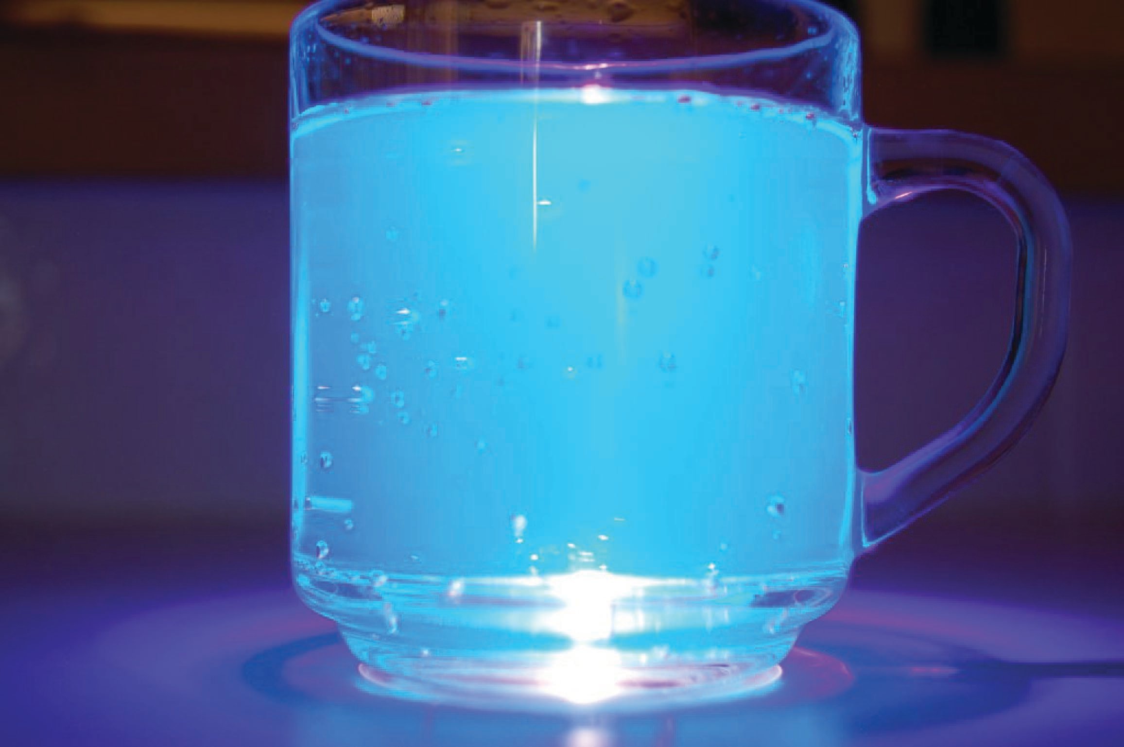
A variety of common food substances fluoresce. Quinine, an ingredient contained in “tonic water,” glows yellow-green when exposed to ultraviolet light:
Olive oil is another example of a food substance fluorescing easily under ultraviolet light. In this case, the color of the emitted light is amber in tone:
Molasses fluoresces a deep green color when exposed to ultraviolet light:

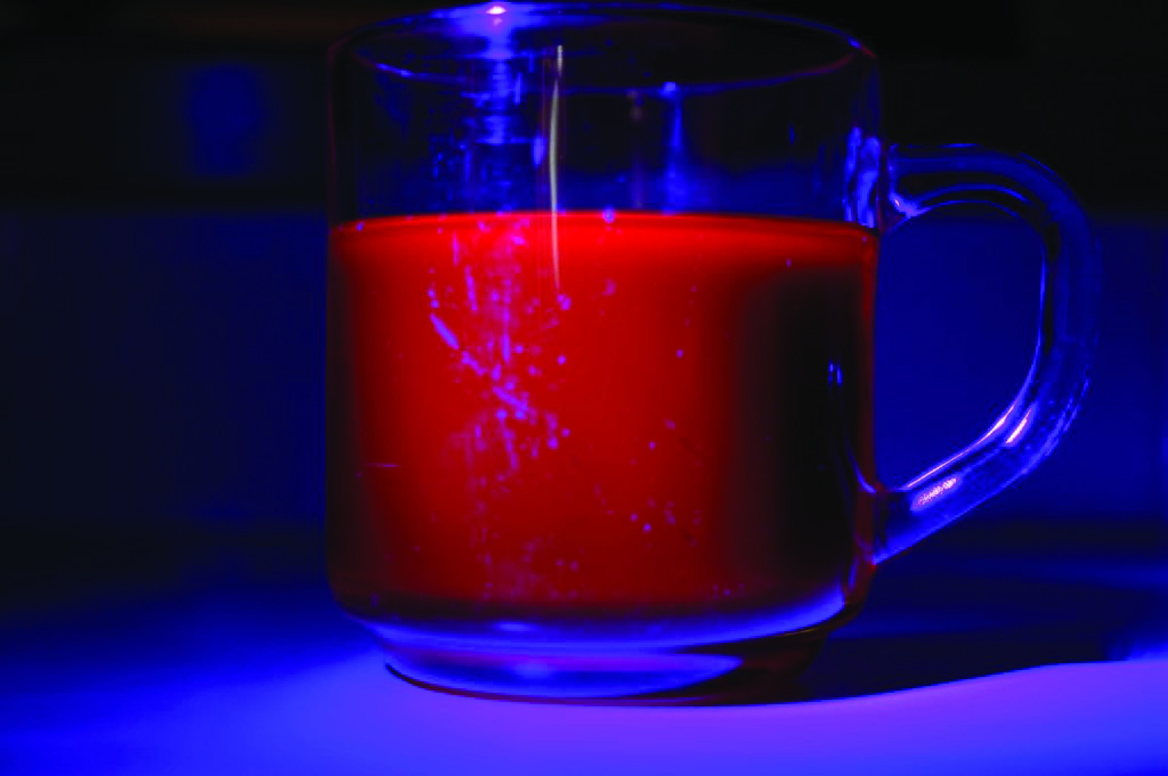
Chlorophyll is an example of a substance (occurring naturally in the tissues of green plants) capable of fluorescence when exposed to ultraviolet light. The color of its fluorescence is red, as shown in this photograph of a house-plant leaf illuminated by a black light:

Fluorescent dyes are often used as “invisible ink,” marking items in such a way as to be invisible under normal light, but plainly visible when exposed to concentrated ultraviolet light. Such ink is used to mark modern United States currency, such as this $20 bill. The fluorescent stripe shown in this close-up photograph contains text reading “USA TWENTY”:

Not all substances fluoresce as easily as others. If a substance present within an industrial sample happens to fluoresce, and all other substances in the sample stream do not (or at least do not to any significant degree), we may apply fluorescence as an analytical technique for the selective measurement of that substance.
Sulfur dioxide (SO\(_{2}\)) is an atmospheric pollutant formed by the combustion of fuels containing sulfur. This gas also happens to exhibit fluorescence under ultraviolet light. A photograph of the fluorescence chamber taken from a Thermo Electron model 43 sulfur dioxide analyzer appears here:
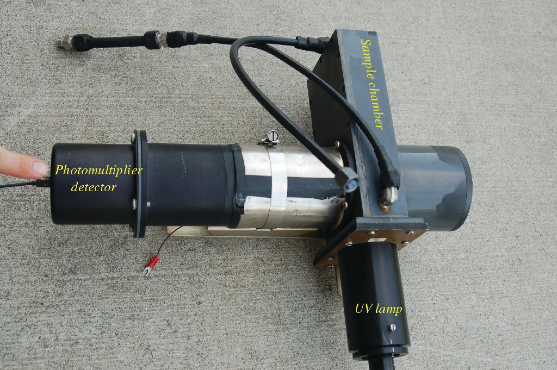
A steady flow of sample gas enters and exits the chamber through the black plastic tubes. Ultraviolet light enters the chamber from a special lamp, and a highly sensitive light detector called a photomultiplier tube measures the amount of light emitted when SO\(_{2}\) molecules inside the chamber fluoresce. The greater the concentration of SO\(_{2}\) molecules in the gas mixture, the more light will be sensed by the photomultiplier tube for any given amount of ultraviolet light.
The incident ultraviolet light from the lamp cannot directly reach the photomultiplier tube, because there is no straight-line path from the lamp to the tube, and the interior walls of the chamber are non-reflective. The only way for the tube to receive light is if molecules inside the chamber fluoresce when excited by the lamp’s ultraviolet light. This ensures the instrument will truly measure fluorescence, and produce a “zero” output when no fluorescent molecules are present.
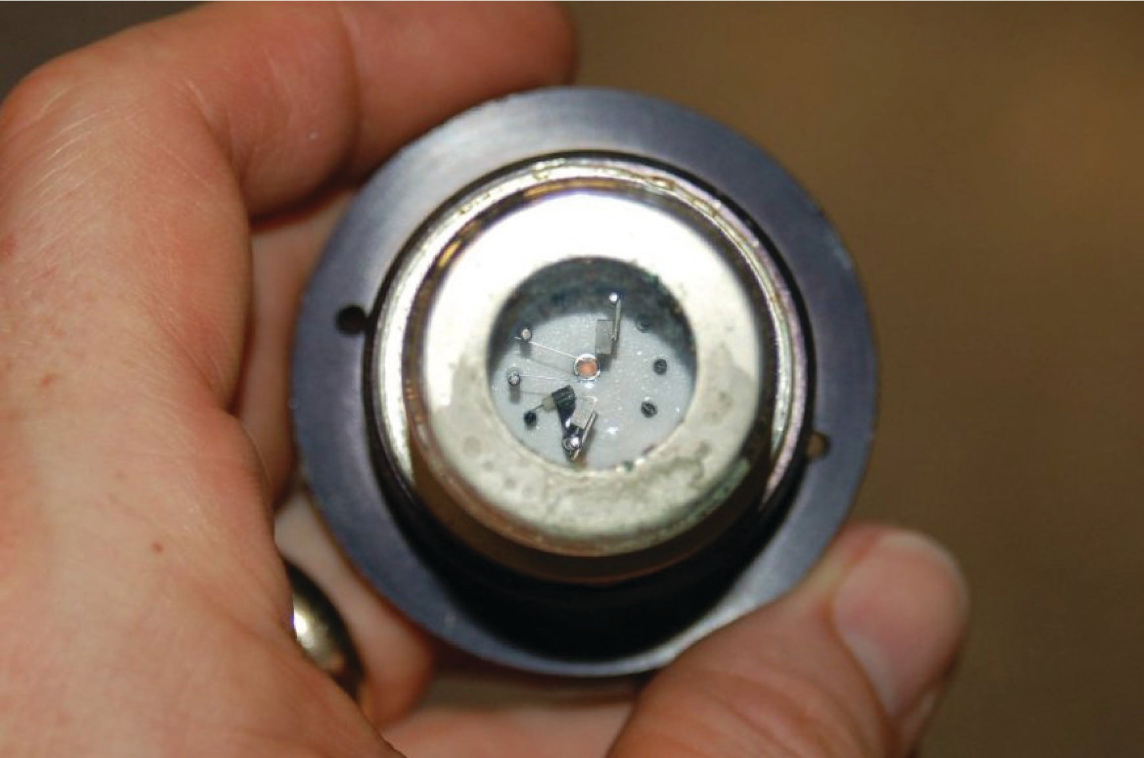
A close-up view of the ultraviolet emitter shows it to be a gas-discharge lamp. When an oscillating source of high-voltage electricity energizes the electrodes inside this lamp, an arc forms and emits pulsating rays of ultraviolet light:
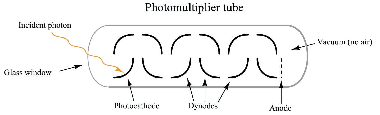
The photomultiplier tube is a special vacuum tube operating on the principle of the photoelectric effect, whereby an incident photon (light particle) of sufficient energy ejects an electron upon striking a metal surface. Light entering a transparent glass window on the photomultiplier tube causes electrons to be emitted from an electrically-charged metal plate called the photocathode. Following the photocathode plate are a series of additional metal plates called dynodes, each one at a successively greater positive potential to provide kinetic energy to electrons attracted toward them. Each time electrons strike a dynode plate at high energy, even more electrons are emitted in a process called secondary emission. The result of secondary emission is that a multitude of electrons reach the final plate (called the anode) for each single photon striking the photocathode: the tube’s action effectively multiplies the effect of each photon for maximum sensitivity. A relatively strong pulse of electric current measured at the anode signals the tube’s reception of each photon:
A simplified photomultiplier tube and power supply circuit are shown here:
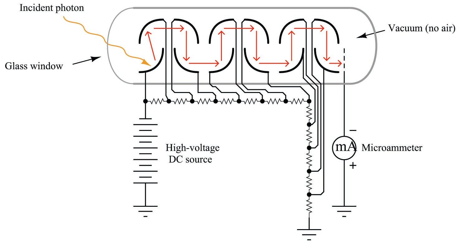
In a real instrument, the micro-ammeter would be replaced by an amplifier circuit, producing a strong electrical signal in direct response to received light intensity. In the case of a fluorescence analyzer, the amplifier’s output signal becomes a representation of SO\(_{2}\) molecule concentration inside the chamber.
Like any other type of analyzer technology, we must be aware of potential interfering substances as we use fluorescence to detect the concentration of the species of interest. Not only does sulfur dioxide fluoresce when exposed to ultraviolet light, but so does nitric oxide (NO) and many hydrocarbon components, especially those large hydrocarbon compounds classified as polynuclear aromatic hydrocarbons or PAH. Unfortunately, both nitric oxide and PAH compounds are produced in some industries where sulfur dioxide is an environmental concern. In order for a fluorescence-based SO\(_{2}\) analyzer to only measure the concentration of sulfur dioxide in a gas stream possibly containing NO and/or PAH compounds, special care must be taken to eliminate the interference.
Fortunately for us, nitric oxide happens to fluoresce at a different wavelength than sulfur dioxide gas. This gives us the ability to de-sensitize the instrument to nitric oxide by placing an appropriate optical filter in front of the photomultiplier tube. This filter blocks light wavelengths emitted by the fluorescence of nitric oxide, so that the photomultiplier tube cannot “see” the fluorescence of NO gas molecules.
The light from hydrocarbon compound fluorescence happens to overlap the spectrum of fluorescent light from SO\(_{2}\) and therefore the problem of hydrocarbon interference cannot be solved by optical filtering. Instead, this SO\(_{2}\) analyzer handles the PAH interference problem by physically filtering out hydrocarbon gas molecules prior to the sample entering the fluorescence chamber using a device called a kicker. The “kicker” is a form of molecular sieve, separating the hydrocarbon molecules from the other molecules in the sample stream so that no hydrocarbon molecules ever enter the instrument’s fluorescence chamber.
After processing by the electronic circuits of the analyzer, the photomultiplier tube’s output signal becomes a representation of SO\(_{2}\) concentration, displayed on an analog meter movement:
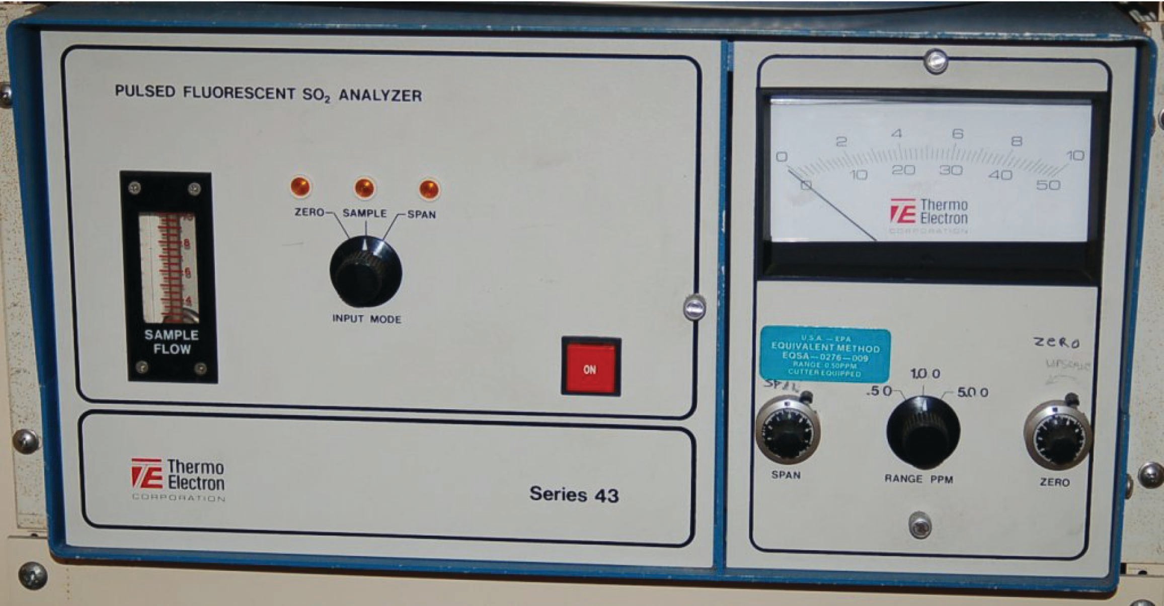
As indicated by the selector switch below the meter face, this instrument has three different display ranges: 0 to 0.5 ppm (parts per million), 0 to 1.0 ppm, and 0 to 5.0 ppm. A different selector switch on the left-hand side of the control panel operates solenoid valves allowing either the process sample gas or one of two different calibration gases to enter the analyzer. The “zero” calibration gas contains no sulfur dioxide at all, thus providing a base-line reference for adjusting the 0% point of the analyzer. The “span” calibration gas contains a precise mixture of sulfur dioxide and some non-fluorescing carrier gas, to serve as a chemical reference for some point near the analyzer’s upper range limit. These calibration gases are commercially available from chemical laboratories, with instrument technicians commonly referring to them as zero gas and span gas. Of course, the composition of any “zero” or “span” gas depends entirely on the type of analytical instrument. What may suffice as a span gas for this sulfur dioxide analyzer would certainly not suffice as a span gas for a multi-component chromatograph or for an NDIR analyzer configured to measure carbon monoxide.
Pressure regulators ensure proper gas flow conditioning in and out of the analyzer. A vacuum pump (not shown in any of the photographs) draws sample gas through the analyzer and provides the necessary differential pressure for the hydrocarbon “kicker” to work:
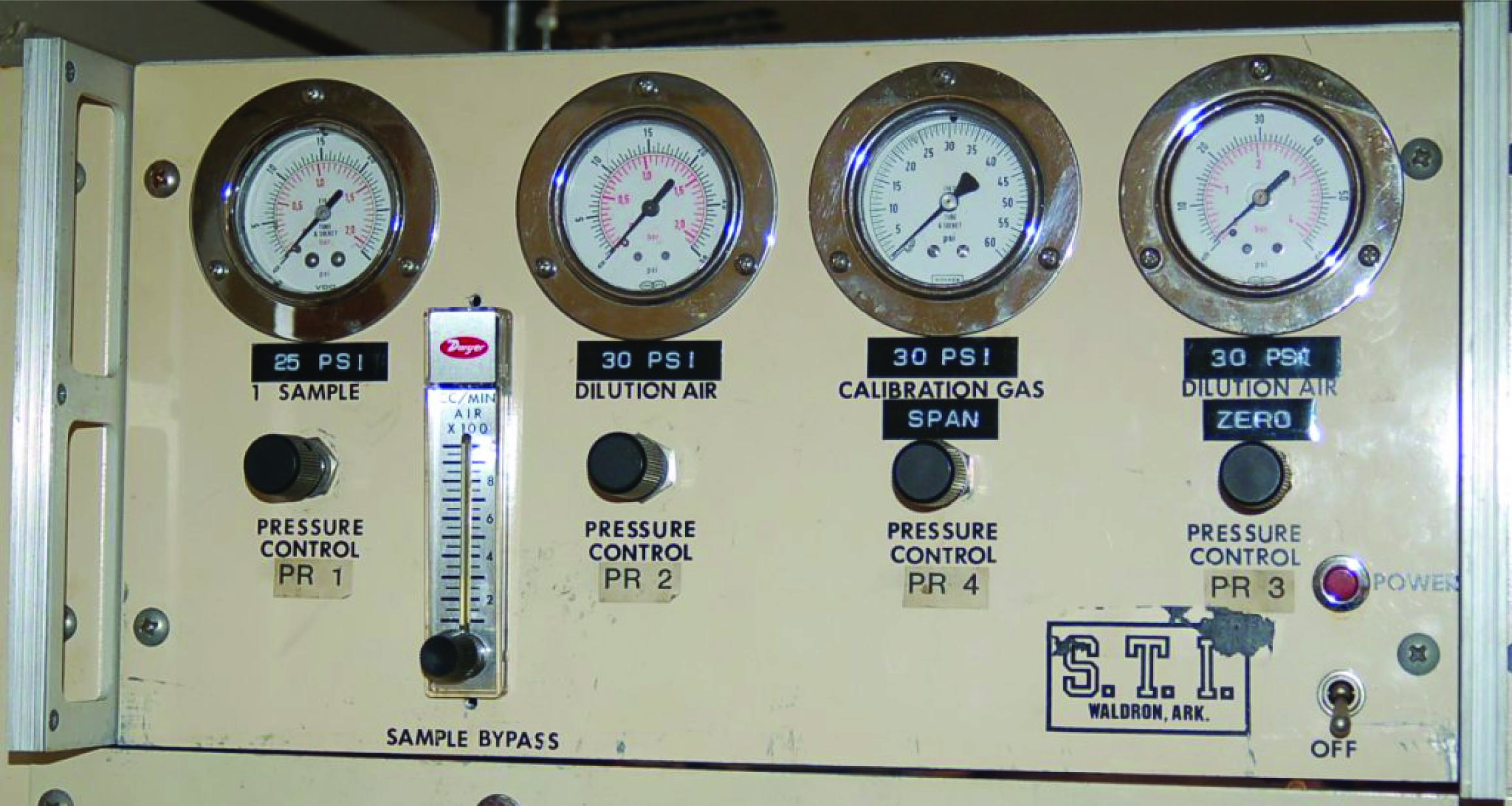
The amount of sample gas pressure is a critically important parameter for this and other optical gas analyzers, because pressure has a direct effect on the density of the gas sample, and therefore on the number of gas molecules per unit volume. If a gas sample of constant species concentration (i.e. a constant parts-per-million proportion of the gas of interest compared to the balance of the gas) happens to increase in pressure, there will now be more molecules of light-absorbing (or light-emitting) gas in that sample, which will register as a higher concentration even though the actual concentration (in percent or ppm or ppb) has not changed. This is why pressure regulation is so important for gas analyzers: an unstable sample gas pressure will result in measurement errors.
