ABB Inverter(slave) + MAX485 + Arduino(master) : 0xE0 (ModbusMaster invalid response slave ID exception)

Thank you for the additional information. You should be able to achieve successful communications with this setup. Are you receiving an error when doing this? If so, what error? If not, what makes you believe communications is not successful? Please detail what you mean by, "There was no success."


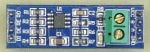
I don't understand what you're trying to do by placing a jumper wire across the ends of R7. This shorts A and B together. Luckily, according to the datasheet, the MAX485 driver's are short-circuit current limited and it has thermal shutdown circuitry, otherwise you would have damaged the MAX485. There is no possible way this could have resulted in successful communication. Your indication of "connected" or "not connected" must not be reliable and is not providing you with the actual status of the RS-485 communication.


In order to identify where the problem lies, please follow my previous recommendation:
Please verify that the inverter is still successfully working using your computer, Modbus Poll, and USB/RS-485 adapter. Please also verify that the Arduino/MAX485 board are still successfully working using your computer, Modbus Simulator, and USB/RS-485 adapter.

Regarding connecting a MAX485 transceiver directly to your Arduino using a breadboard, you could certainly give this a try, but I doubt you will see any difference versus the MAX485 board that you've removed R7 from (assuming that board has not been damaged). If you do try this, you will need to have a pull-up resistor on the RO signal, since that output from the MAX485 is high impedance when RE is high. You may be able to simply enable an internal pull-up on the Arduino's RX pin in code:
https://www.arduino.cc/en/Tutorial/DigitalInputPullup

Thank you for responding!

After removing R7, I still get error E2 (timeout error).

Sorry, I also don't really understand what happened when connecting the resistor terminals, but what appeared in the serial was what I expected to get (figure 1).

To use only the MAX485 CI I need to put only one pull up resistor (10kohm), ok?

1608150198327.png
 
After removing R7, I still get error E2 (timeout error).
OK. This is different from the 0xE0 error you were originally getting. A timeout error is typically caused by one of two things (assuming hardware has not been damaged): wiring or configuration settings.

Please triple-check that you have your RS-485 +, -, and GND connections correct and the S1:1 on the inverter is in the OFF position. Try swapping the + and - wires, just in case you have them connected backwards.

Please also confirm that the following items match in both your Arduino code and the inverter's Modbus RTU parameters:
  • Baud Rate
  • Parity
  • Number of Stop Bits
  • Modbus Slave Address (i.e. address of the inverter and the address you're targeting in the Arduino's Modbus requests)
  • Request Timeout (Arduino only, make sure this is sufficiently high, for example try setting it to 1 second)

Sorry, I also don't really understand what happened when connecting the resistor terminals, but what appeared in the serial was what I expected to get (figure 1).
It's not possible for communication to work while the A and B lines are shorted together, but if you were making this connection while the devices were powered and then removed the jumper wire, it may have allowed communications to work momentarily. It would be more helpful if you could add debug printing to your Arduino program indicating when it transmits a request, the transmit buffer contents, whether a valid response was received or an error occurred, and the received buffer contents (if any).

To use only the MAX485 CI I need to put only one pull up resistor (10kohm), ok?
Yes, you should only need to add a pull-up to the RO/RX signal for communications to work. You can do one of the following:
1. Install a 10k ohm resistor between RO and VCC
2. Turn on the Arduino's internal pull-up resistor on its RX input pin
 
Yes, you should only need to add a pull-up to the RO/RX signal for communications to work. You can do one of the following:
1. Install a 10k ohm resistor between RO and VCC
2. Turn on the Arduino's internal pull-up resistor on its RX input pin

Hi.
I used only the MAX485 with the 10k resistor as you suggested, I had no results. Then just take the CI and connect it to the inverter (without polarization and termination resistors) and I managed to establish the communication (Fig 1).
This for 1 inverter. I have to put 3 inverters in an rs485 network and for that I think I have to insert the terminating resistor..this is my next step.
I thank you for all the time you spent helping me. Thank you!


1608572568519.png
 
I'm confused about what you did to get it to work. Please clarify so that others reading this that may have the same issue have a clear understanding of what you did wrong (and what they may be doing wrong on their own setup).

What's the difference between this:
I used only the MAX485 with the 10k resistor as you suggested, I had no results.
And this:
Then just take the CI and connect it to the inverter (without polarization and termination resistors) and I managed to establish the communication (Fig 1).
Could you please detail the connections you made, or better yet, share a drawing?

Regarding your other statement:
This for 1 inverter. I have to put 3 inverters in an rs485 network and for that I think I have to insert the terminating resistor..this is my next step.
This is not true, you do not need to install terminating resistors just because you have more devices on the bus. Only if the total length of the bus becomes very long (refer to my table in post #33).
 
I'm confused about what you did to get it to work. Please clarify so that others reading this that may have the same issue have a clear understanding of what you did wrong (and what they may be doing wrong on their own setup).
Hi, Sorry for the delay.
I made the connection between the inverter and the Arduino with a MAX485 integrated circuit (figure). I didn't modify the code.

1609844925383.png

I think one of the resistors in the module I used before was preventing the signal from reaching the arduino.

Thank you for your help!
 
The MAX485 CI has 8 pins. I connected them to the Arduino as follows:

VCC --- 5V ARDUINO
GND --- GND ARDUINO
A ---- A (D + INVERTER)
B --- B (D- INVERTER)
RI ---- RX1 ARDUINO
DI --- TX1 ARDUINO
RE --- PIN 2 ARDUINO
DE --- PIN 3 ARDUINO

THE CODE I USED IS BASED ON THE EXAMPLE OF THE MODBUS MASTER LIBRARY.
NO GREAT MODIFICATIONS WERE NECESSARY.
 
I think one of the resistors in the module I used before was preventing the signal from reaching the arduino.
I encourage you to confirm the exact cause of why it was not working previously. Without knowing what caused the failure, you cannot be sure that you've fixed it. It is likely that you will have the same issue again, unless you identify the cause and confirm that your solution resolves the identified issue.

If the only difference between your working configuration of the MAX485 chip by itself and the configuration of the MAX485 chip and a 10K resistor between RO and VCC, then I highly doubt the resistor is to blame (only a mis-wiring or wrong resistor value would cause a problem, or perhaps you already have an internal pull-up resistor enabled on the Arduino's RX pin).
 
The MAX485 CI has 8 pins. I connected them to the Arduino as follows:

VCC --- 5V ARDUINO
GND --- GND ARDUINO
A ---- A (D + INVERTER)
B --- B (D- INVERTER)
RI ---- RX1 ARDUINO
DI --- TX1 ARDUINO
RE --- PIN 2 ARDUINO
DE --- PIN 3 ARDUINO

THE CODE I USED IS BASED ON THE EXAMPLE OF THE MODBUS MASTER LIBRARY.
NO GREAT MODIFICATIONS WERE NECESSARY.
Thank you for the detailed connection description, however, you are still missing a common GND connection between the Arduino, MAX485, and the inverter.
GND --- GND ARDUINO --- GND INVERTER

Without wiring a common ground connection between all devices, you may see intermittent communication issues. This could lead you to (incorrectly) believe that other things are causing your problem, when in fact all of the communication issues were caused by not connecting ground references together. That being said, this type of issue is far more common in the field rather than on a test bench, since ground references in a lab environment tend to be at the same voltage potential, which is not necessarily true in the field.
 
Thank you for the detailed connection description, however, you are still missing a common GND connection between the Arduino, MAX485, and the inverter.
GND --- GND ARDUINO --- GND INVERTER
Hello. Sorry, but I connected all GND:

GND ARDUINO --- GND MAX485 ---- GND INVERTER
 
Hi ,

I'm trying to achieve the same functionality here. I have used MAX485 with Arduino Uno to communicate with ABB ACS380 VFD .
I'm facing communication challenge . can you Please guide me .
you can reach me @ email [email protected].
Please review all of the suggestions given in this thread. There is a good chance it already answers any communication issue you're having with this equipment. If you're still having issues, please explain exactly what you've tried, the results, any error messages, and the exact issue you're having.
 
Please review all of the suggestions given in this thread. There is a good chance it already answers any communication issue you're having with this equipment. If you're still having issues, please explain exactly what you've tried, the results, any error messages, and the exact issue you're having.
I'm trying to communicate ABB Inverter(ACS880)-MAX485-Arduino(master) using ModbusMaster.h Library .

With the connections as in thread , i;m not able to communicate with the ABB VFD . I have tried connecting Modbus Port GND pin to GND PIn of aurdino. The Termination and Bias switch on VFD is in OFF Position. I have tried Termination and Bias switch on VFD is in ON Position as well but couldn't find much results.
 
Hi ,

I'm trying to achieve the same functionality here. I have used MAX485 with Arduino Uno to communicate with ABB ACS380 VFD .
I'm facing communication challenge . can you Please guide me .
you can reach me @ email [email protected].
Hello. Please explain what problem you are having?

The max 485 converter module didn't work for me, I just used the max485 integrated circuit.

1- Remember to configure the control pins (DE and RE) in the ModbusMaster library;
2- Confirm that the baud rate, parity and slave ID are correct according to the ABB ACS380 VFD manual;
3- Confirm if the addressing is correct and if you considered the offset;
4 - Confirm that you have not reversed the signals from the rs485 cabling. Usually B is - and A is +. But you must confirm with the manufacturer.

I await further explanation of the problem.
 
I'm trying to communicate ABB Inverter(ACS880)-MAX485-Arduino(master) using ModbusMaster.h Library .

With the connections as in thread , i;m not able to communicate with the ABB VFD . I have tried connecting Modbus Port GND pin to GND PIn of aurdino. The Termination and Bias switch on VFD is in OFF Position. I have tried Termination and Bias switch on VFD is in ON Position as well but couldn't find much results.
Hello, when there is only one slave on the modbus network it is not necessary to activate the termination. It's good that you show what error is appearing in the IDE in arduino when loading the code. The ModbusMaster library foresees some situations and returns an error when the connection with the slave is not successful. Please show what error is happening exactly.
 
Hello, when there is only one slave on the modbus network it is not necessary to activate the termination.
Just to again clarify, as I explained in post #44, whether termination is necessary does NOT depend on how many slave devices are on the Modbus network. It depends on the baud rate and total length of the cabling used, as I've listed in post #33.

I'm trying to communicate ABB Inverter(ACS880)-MAX485-Arduino(master) using ModbusMaster.h Library .

With the connections as in thread , i;m not able to communicate with the ABB VFD . I have tried connecting Modbus Port GND pin to GND PIn of aurdino. The Termination and Bias switch on VFD is in OFF Position. I have tried Termination and Bias switch on VFD is in ON Position as well but couldn't find much results.
Please follow my suggestion from post #34:
Here are two ways to resolve your issue. In either case, you need to connect A, B, and GND from your MAX485 board to the inverter's Data +, Data -, and GND terminals (i.e. X1:1, X1:2, and X1:3 or X2:1, X2:2, and X2:3), respectively.

1. Remove R7 from your MAX485 board. Set S1:1 and S1:2 both to the OFF position on the inverter.

2. On the MAX485 board, add one resistor between A and VCC and add another resistor between B and GND. The resistors should be the same value and can have a value of 470, 560, or 680 ohms. On the inverter, set S1:1 to the OFF position and set S1:2 to the ON position.


If you are still having issues, please follow my suggestions from post #42:
Please triple-check that you have your RS-485 +, -, and GND connections correct and the S1:1 on the inverter is in the OFF position. Try swapping the + and - wires, just in case you have them connected backwards.

Please also confirm that the following items match in both your Arduino code and the inverter's Modbus RTU parameters:

  • Baud Rate
  • Parity
  • Number of Stop Bits
  • Modbus Slave Address (i.e. address of the inverter and the address you're targeting in the Arduino's Modbus requests)
  • Request Timeout (Arduino only, make sure this is sufficiently high, for example try setting it to 1 second)

Note that you may need to power cycle the inverter after changing communication settings for them to take effect.

If you are still having issues, please provide the exact error code or message you are receiving in your ModbusMaster library.
 
Hello , I Have rs485 to ttl converter module (same as the mentioned previously) with esp32 flashed with esphome code to read the data from MUST solar inverter , the problem is i have to power on the module and the esp32 first (from power bank or usb otg , etc ..) with everything connected to the inverter and then restart the inverter in order start getting the data , if the inverter not restarted there is no data , what could be the cause of this problem? , i don't want to restart the inverter every time i connect or disconnect the power from the esp and the module
 

Attachments

R7 is removed , i attached the pin out i use , i tried every pinout you can Imagin and this the only one that works great for me after restarting the inverter
Screenshot 2024-01-27 010042.pngphoto_2024-01-27_01-03-20.jpg photo_2024-01-27_01-03-26.jpg
 
I believe that RS-485 module requires 5V, so the issue may be caused by powering it using 3.3V instead of the required 5V.

Additionally, you really should have 3 wires between the RS-485 module and the inverter (+, -, and ground). Without that 3rd ground wire, the two devices may not share the same 0V reference for the RS-485 signals and may have communication issues.

Otherwise, it's hard to say exactly what the cause could be without more details, but here is one additional possible explanation.

When the ESP32 first powers up, it may be driving its RS-485 output before the ESPHome code puts the RS-485 driver into an idle state. This could be putting the inverter into some bad state which prevents it from successfully receiving packets again (this would commonly be known as a firmware bug).

Try my above suggestions first, and if you're still having the issue, try this:
What happens if you keep your RS-485 wires (you are using 3 wires, right?) disconnected from either the inverter or the RS-485 module, power up all equipment, then connect the RS-485 wires?
 
I believe that RS-485 module requires 5V, so the issue may be caused by powering it using 3.3V instead of the required 5V.
I realized that this comment may lead you to try to power the RS-485 module with 5V, while still using the 3.3V-powered ESP32. Don't do that.

According to this guide (https://learn.sparkfun.com/tutorials/esp32-thing-hookup-guide/hardware-overview), the ESP32's I/O pins are NOT 5V tolerant, so you either need to use a different RS-485 module that takes 3.3V power, or add a level shifter device.
 
Additionally, you really should have 3 wires between the RS-485 module and the inverter (+, -, and ground). Without that 3rd ground wire, the two devices may not share the same 0V reference for the RS-485 signals and may have communication issues.
already tried that and makes no difference , maybe i was not clear, first : esp32 and the RS-485 module are powerd on in the same time (as the RS-485 module is powerd from the esp32 3.3v) and the RS-485 module is connected to the COM Port on the Inverter side, and then i power on the inverter and everything works and all data showing, * in case the inverter was already on and i connected the RS-485 module to the COM port NO data comes up and i have to restart the inverter in order to start working
 
Top