Capacitors in Old I&C drawings

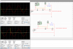
Hi guys, thanks for your support. Just joined the world of Electrical & Industrial I&C. Was going through some old legacy drawings for work and found something interesting. HLP and LLP are relays. PIA-1 is a pressure sensor which is tied to an annunciator panel. I am having trouble understanding the circuit, from what I can tell both Hi and Lo points are high impedance at normal pressure levels (in which case the Relay coils are always engaged). As soon as a fault condition is detected, one of the Hi, Lo points will go to zero impedance thereby deactivating their corresponding relay. I am guessing the resistor is current limiting. Is my understanding correct, and if so what is the purpose of the capacitor in that circuit (I believe its a 1uF Cap)?

121173630_792880388175418_8728364586269180509_n.jpg
 
It is unusual to de-energise a relay by diverting coil current through sensing
device contacts. However we can only see a small part of the circuit to work out
the reasoning behind it's original design.

We can only guess that the supply is not DC as capacitors C51/61/71 provide AC coupling.
If it is AC supply, each capacitor will give a voltage drop inversely proportional to the
frequency without absorbing power (except a little leakage and reactive power).

If you know the supply frequency you should be able to calculate capacitor impedance
and therefore current through R51/61/71 which should be relatively constant.
 
Yes, I thought the same thing. The design however is from 1950's and I am assuming instrumentation and sensors worked quite differently back then. The supply is 120 VAC, 60 Hertz (Not 25 VDC). I am also assuming controllers either didn't exist or were fairly new back then.

This is definitely what my assumption was, the capacitor is present to provide some sort of impedance in the circuit. I have just never seen impedance used this way and nor circuits like this. Thank you for your answer oneye14!
 
ControlSystemGuru; OneEye14. . .
AC-powered control systems were not unusual in the '50s ! I began my controls career in 1952; started my controls engineering company "Automation Engineering" in 1955. My conclusion about the circuit in question is that it served that period's "fail-safe" function:
a) It is an AC Supply.
b) Min current-draw in both the HLD and LLD branches occurs when both relays are energized, or "System Normal".
c) Max current-draw occurs in either the HLD or LLD branches when an "Off-Normal-High" or "Off-Normal-Low" condition exists.
d) For Power-Loss, both High and Low function relays are de-energized (tripped).
Regards, Phil Corso
Thank you Phil. What might be the purpose of the capacitor there? I understand the resistors limit current when HLP or LLP is trigger i.e the current patch will go through the PIA-1 sensor. Very interesting idea indeed.
 
ContolSystemsGuru...
The only fact I can come up with is that current-draw is virtually lossless in a capacitor ! Thus, total power losses are contributed by the resistor and relay! But, then I ask myself, why the resistor at all ?
Phil
 
ContolSystemsGuru...
I'm now convinced this is a simple R-L-C timing circuit to continuously increase some process level and then reverse the process. Of course the key device is PIA-1. It must be "switched" at each extreme ! For example, a simple SPDT switch, possibly for a Bag or Container filling machine.
Phil
That would be brilliant yet over kill I think. They did have timers and flashers back in the 50's. I do think your initial hypothesis was correct. PIA-1 is a pressure sensor with two high Impedance inputs (Like a comparator Op Amp, in fact it possible this device is just two comparator op amps preset to high and low values). PIA-1 also has an internal relay.

When the process pressure is between high and low i.e nominal levels, both inputs are high impedance.
This forces current through coils HLP and LLP. These coils are always engaged and tied to an annunciator panel with a NC type relay.

When the pressure exceeds or drops below nominal levels, one of the two inputs goes to low impedance i.e if pressure exceeds, input HI on PIA-1 will go to low impedance and consequently coil HLP will disengage. Similarly if pressure falls low, input LO on PIA-1 will go to low impedance and coil LLP will disengage. Hence the relay at the annunciator will also close and a light will go on. In either case the resistor serve as current limiting.

I could be totally wrong here but seems like the most logical explanation. The capacitor might be there because the designer had a misconception, or tried to introduce impedance in the circuit. I have seen older drawings with tones of diodes in random places due to a misconception at the time. It could also be that this designer was smart and figure that if any of the two PIA-1 inputs went to low impedance suddenly, the coil which is an inductor would discharge straight to ground via PIA-1. The capacitor might be there to counter that discharge.

Either way this is a great discussion! Thanks PhilCorso!
 
According to my understanding CAPACITORS are use to store electrical energy which can be used by the circuit when required.
This is their general definition/purpose. But they are used widely in all kinds of circuits, from filters to power supply stabilizers, timing and flashing circuits etc. They can also be used to block DC entirely sometimes.

I simulated this circuit using Multisim earlier to see the differences with and without the capacitor with some interesting results. I used a simple SPST switch to simulate the PIA-1 device.

As you can see the voltage surges rapidly past 120 for brief moment across the switch (PIA-1) as soon as it opens in the circuit without the Capacitor. Its probably seeing voltages past what it was designed to handle, hence the Capacitor smooths it out as seen in the first circuit picture.
 

Attachments

Sorry guys but Screenshot_1 is very misleading.
What is the current consumption in both circuits ?

What you have is a coil having current removed.
Even a DC circuit will spike in a similar manner,
so is the transient not directly proportional to current ?

"According to my understanding CAPACITORS are use to store electrical energy which can be used by the circuit when required."
Capacitors are cute things that do all sorts of curious things, like tuned circuits,
frequency dependent feedback components and other appliations where temporary
storage of energy is hard to imagine.

The capacitor in this circuit should be considered as a current source.
If you cannot believe it, replace the relay coil with a suitably sized resistor
then check voltages/currents at each stage.
Better still, build your own transformerless power supply (220vAC to 12vDC)
using similar layout but replace the relay coil with bridge rectifier,
smoothing capacitor and resistive load.
 
@oneye14 Apologies, I made the simulation quickly and didn't think of presentation. I will check current consumption and let you know. This is an old I&C circuit from the 50's and I was confused as to the role of the 1uF capacitor.

By current source do you mean it sources constant current?

"Better still, build your own transformerless power supply (220vAC to 12vDC)
using similar layout but replace the relay coil with bridge rectifier,
smoothing capacitor and resistive load. "
How exactly will 220 be stepped down to 12?
 
"By current source do you mean it sources constant current?"
Not exactly but if you have a constant voltage source and
fixed frequency the capacitor will have a fixed impedance which
is easily calculated.

You will notice from circuit supplied that most of the voltage drop
is across the capacitor. The caveat is that it is unwise to o/c
(open circuit) supply to the relay coil which is why the pressure
switch maintains the circuit.

Because the circuit is so simple it is easy to build and check results;
mindful of the fact the capacitor must be rated for the peak AC voltage
in the circuit. The UK has 240vAC which gaves a capacitor rating over
350v. Capacitor peak current is harder to define and not always specified
which is why the occasional transformerless power supply has a short circuit
capacitor and the current limit resistor catches fire melting the case housing.
 
Gentlemen...
The relay function can't be represented as a "Bridge". They are inductive ! And their H or mH have been lost to us mere mortals forever!
Stay well, Phil
 
Top