Facebook
 Google
 GitHub
 Linkedin
Hello all,
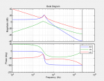
I'm designing a voltage-mode controller buck converter. I have derived the plant transfer function as well as the PID controller, calculated the loop-gain and once i was satisfied with the phase-margin i am now ready to verify via PSIM.
The PSIM circuit is attached. The output voltage is sampled via an ADC, compared to a reference value to generate the error which is the input of the PID (H(z)). The sampling frequency of the ZOH and H(z) is 500kHz as is the switching frequency of the converter.
Would appreciate any comments on the simulation. In addition, how can i verify the relationship between the frequency derivation in matlab to the time domain results obtained in PSIM.
Thanks!
Tom
Attachments
-
 25.1 KB Views: 96
 -
 26.5 KB Views: 189