Facebook
 Google
 GitHub
 Linkedin
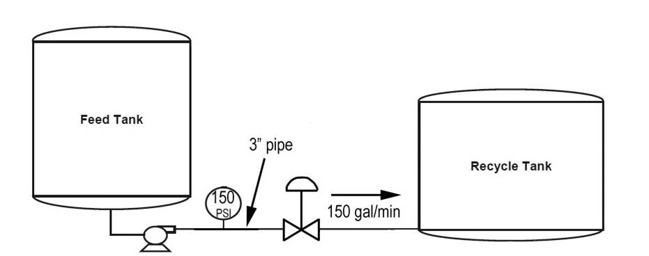
Hi guys, I have this as school project and I am stuck at the moment and any help would be great. So I need to make simulation of flow regulating system that will have proportional valve as element of control. System needs to take in consideration transport delay and non-linearity of valve (dead-band mainly, histeresys and asymmetry should not be taken in consideration). I need to make software for it in TIA portal and simulation in WinCC. So far I made system which is shown in picture below and if I can I would like to keep it like that(elements of system), if not it can be changed of course. Frictions from pipes don't have to be taken in consideration also and whole system is in one line but I didn't have room to draw it properly(tanks should be aligned).
I made some mathematical modeling and came with this:
P = dp * Q (pump power)(1)
pPump = p1 + dp (pressure on pump exit)(2)
Q = Cd0 * i / i_max * A0 * sqrt(2*(pPump - p2)/rho), (prop. valve equation)(3)
Implementing equation 1 into equation 2 into equation 3 I get this:
Q^2 = (Cd0 * i / i_max * A0)^2 * (2*( p1 + P / Q - p2)/rho)
which is:
Q^3 - (Cd0 * i / i_max * A0)^2 * (2*( (p1 - p2) * Q + P)/rho) = 0
and that is qubic equation
Q^3 + a1 * Q + a0 = 0, (4)
with coefficients:
a1 = - (Cd0 * i / i_max * A0)^2 * 2 * (p1 - p2) / rho
a0 = - (Cd0 * i / i_max * A0)^2 * 2 * P / rho
when solved it should give value of flow in system but I get some weird values for flow rate with that or I get good result but in weird measuring unit. I also made HMI in simulation to enter parameters for valve, pump, etc. and I get some values for flow but I am not sure that is correct. Also I have PID regulator made in software so I just need to enter parameters for it. Don't know if I need to make some linearisation or it is already linearized system? So any help with this would mean so much to me. And sorry for my bad english.