Hi
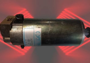
We are having GE Frame 6B DLN Gas turbines. The original flame scanners (Reuter Stokes) which came with these turbines were facing repeated fluctuation problems in their readings and these fluctuations utlimately were becoming so low that we had to take turbine shutdowns to clean the scanners. We usually have high humidity in our environment and according to some documents, the high humid air finds a cooler surface on the scanner glass in the combustion chamber and thus condenses causing foggy conditions on the glass resulting in flame reading fluctuation. This cooler surface is present because these GE scanners are provided with a water cooling provision so that they can survive in a temperature excess of 200 degC.
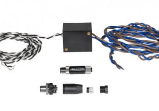
With this in mind, we installed a 3rd party scanner with remote electronics so that we do not have to do any water cooling on the scanner. The hot end of this assembly is rated for 350 deg C, and through which a HT rated fibre optic cable runs to a cool end electronic enclosure which converts the reading to 4-20mA and provides to Mark VI control system.
We installed this scanner as a trial as one of the four secondary scanners. The scanner test proved to be very successful and we observed, during operation of the turbine, that it behaves well in comparison to the other secondary scanners and we found no lagging response when the secondary flame was ON and OFF.
We need to do a risk analysis as whether using these 3rd party scanners will compromise machine safety in any respect or not. I see immediately two main risks here:
Risk#1) What if the 3rd party scanner does not detect the flame?
If this happens then the machine will simply trip or will not start and the machine safety will be intact. What do you think?
Risk#2) What if the 3rd party scanner false detects the flame (means the flame is not there but even then it detects)?
This is a debatable scenario. I need your help here. Please let me know if there is any other way in machine parameters which can confirm that the flame is there or not. How machine can be saved in this regard?
I'm sure that the moment we will discuss this matter with turbine OEM, they will take it as a business case and will try to convince us that using non-OEM scanners will pose machine to the safety risk. But I want them to come to technical terms. If my scanner false detects the flame, how my machine safety can be still ensured. By the way this will be very rare case (almost unimaginable) as I have told you that we have tested this scanner on the same machines. But still, can you help me in figuring out any further risk which may get raise?
Regards


